
2024 question paper
Computer Networks
26 questions
Q1a. Consider the following: 1. Twisted pair cables 2. Microwaves and Satellite Signals 3. Repeaters 4. Analog Transmissions 5. Fiber optics Which of the above is considered as (a) signal transmission medium in data communications? (i) (1) and (5) (ii) (1) (2) and (5) (iii) (1) and (2) (iv) (1) (2) (3) and (5)20242m
Module 1: Physical Layer & Data Communication
View this question on its own page →Consider the following:
- Twisted pair cables
- Microwaves and Satellite Signals
- Repeaters
- Analog Transmissions
- Fiber optics
Which of the above is considered as (a) signal transmission medium in data communications?
(i) (1) and (5)
(ii) (1) (2) and (5)
(iii) (1) and (2)
(iv) (1) (2) (3) and (5)
Worked SolutionAnswer: (ii) (1) (2) and (5)
A transmission medium is the physical path over which the signal travels from transmitter to receiver; media are either guided (wired) or unguided (wireless). Twisted pair (1) and fibre optics (5) are guided media, while microwaves and satellite signals (2) form the unguided category. All three carry the signal itself, so (1), (2) and (5) are correct, which is option (ii).
Repeaters (3) are active network devices that regenerate and retransmit a weakened signal - they sit on the medium but are not a medium themselves. Analog transmission (4) is a signalling technique (how bits are represented as a waveform), not a medium.
The remaining options fail for a single reason each: (i) omits the unguided medium (2), (iii) omits fibre (5), and (iv) wrongly includes the repeater (3), which is a device rather than a medium.
Q1b. On a simplex data link, which of the following is a possible error recovery technique? (i) Backward error correction (BEC) (ii) Automatic Repeat Request (ARQ) (iii) The use of hamming codes (iv) Downward error correction (DEC)20242m
Module 2: Data Link Layer & MAC Sublayer
View this question on its own page →On a simplex data link, which of the following is a possible error recovery technique?
(i) Backward error correction (BEC)
(ii) Automatic Repeat Request (ARQ)
(iii) The use of hamming codes
(iv) Downward error correction (DEC)Worked SolutionAnswer: (iii) The use of hamming codes
On a simplex link, signals travel in one direction only, so there is no return channel on which the receiver can send acknowledgements or NAKs. Any error-control scheme that depends on feedback is therefore impossible on such a link.
Hamming codes are forward error correction (FEC): the sender appends check (parity) bits, and the receiver uses them to detect and correct errors locally, entirely at the receiving end. No reverse path is needed, so Hamming coding is the only workable technique among the choices.
ARQ (ii) requires ACKs and retransmissions to flow back from receiver to sender - exactly what a simplex link cannot provide. BEC (backward error correction) and DEC (downward error correction) are not recognised error-control terms; the two real families are FEC and retransmission-based ARQ, so (i) and (iv) are distractors.
Q1c. In specific, if the systems use separate protocols, which one of the following devices is used to link two systems? (i) Repeater (ii) Gateway (iii) Bridge (iv) Hub20242m
Module 3: Network Layer & Routing
View this question on its own page →In specific, if the systems use separate protocols, which one of the following devices is used to link two systems?
(i) Repeater
(ii) Gateway
(iii) Bridge
(iv) HubWorked SolutionCorrect answer: (ii) Gateway
A gateway connects networks or systems that use different protocols and can translate between those protocols, allowing otherwise incompatible systems to communicate.
- Repeater: Operates at the physical layer and regenerates signals; it does not translate protocols.
- Bridge: Operates at the data-link layer and forwards frames between LAN segments using compatible link-layer protocols.
- Hub: A multiport repeater that sends incoming bits to its other ports; it does not perform protocol translation.
Exam tip: When a question specifically says that two systems use different protocols, the expected answer is generally Gateway.
Q1d. Which of the following cannot be used as a medium for 802.3 ethernet? (i) A thin coaxial cable (ii) A microwave link (iii) A twisted pair cable (iv) A fiber optical cable20242m
Module 2: Data Link Layer & MAC Sublayer
View this question on its own page →Which of the following cannot be used as a medium for 802.3 ethernet?
(i) A thin coaxial cable
(ii) A microwave link
(iii) A twisted pair cable
(iv) A fiber optical cableWorked SolutionAnswer: (ii) A microwave link
IEEE 802.3 defines Ethernet over wired (guided) physical media only. The other three choices are all standard 802.3 media: thin coaxial cable for 10BASE2 (i), twisted pair for 10BASE-T, 100BASE-TX and 1000BASE-T (iii), and optical fibre for 10BASE-F and the 1000BASE-SX/LX variants (iv).
A microwave link (ii) is an unguided wireless medium. Wireless media belong to the IEEE 802.11 (Wi-Fi) family of standards, not to 802.3, so microwave cannot serve as an 802.3 Ethernet medium.
Q1e. Which of the following is correct IPv4 address? (i) 124.201.3.1.52 (ii) 300.142.210.64 (iii) 01.200.128.123 (iv) 128.64.0.020242m
Module 3: Network Layer & Routing
View this question on its own page →Which of the following is correct IPv4 address?
(i) 124.201.3.1.52
(ii) 300.142.210.64
(iii) 01.200.128.123
(iv) 128.64.0.0Worked SolutionAnswer: (iv) 128.64.0.0
A valid dotted-decimal IPv4 address has exactly four octets separated by three dots, every octet in the range 0-255, and no leading zeros (a leading zero would be read as octal).
- (i)
124.201.3.1.52has five octets, so it is not a 32-bit dotted-decimal address. - (ii)
300.142.210.64contains the value 300, which exceeds 255. - (iii)
01.200.128.123begins with a leading zero, which is invalid/ambiguous. - (iv)
128.64.0.0has four octets, each within 0-255, so it is a legal IPv4 address (it is also a Class B address).
- (i)
Q1f. The checksum in IP must be recomputed at every router because of change in ____ fields. (i) TTL, Options, Identification Number, Offset (ii) TTL, Options, Data, Offset (iii) TTL, Options, Datagram Length, Offset (iv) TTL, Header Length, Offset, ToS20242m
Module 3: Network Layer & Routing
View this question on its own page →The checksum in IP must be recomputed at every router because of change in ____ fields.
(i) TTL, Options, Identification Number, Offset
(ii) TTL, Options, Data, Offset
(iii) TTL, Options, Datagram Length, Offset
(iv) TTL, Header Length, Offset, ToSWorked SolutionAnswer: (iii) TTL, Options, Datagram Length, Offset
The IP header checksum is computed over the IP header only (the payload is excluded), so any change to a header field invalidates the stored checksum. A router always decrements the TTL field before forwarding, which by itself forces recomputation. The Options fields (record route, timestamp, etc.) may be updated by routers along the path. If the router must fragment the datagram, every fragment gets a new datagram (total) length and a new fragment offset, so each new header needs a fresh checksum.
The data (ii) is not covered by the header checksum, so it can never trigger recomputation. The identification number (i) is copied unchanged from the parent datagram into each fragment - its job is to tie the fragments together - so it does not change during forwarding. Header length and ToS (iv) are also not rewritten by a normal forwarding router, so they are not the reason for per-hop recomputation.
Q1g. Which of the following statements could be valid with respect to the ICMP (Internet Control Message Protocol)? (i) It reports all errors which occur during transmission. (ii) A redirect message is used when a router notices that a packet seems to have been routed wrongly. (iii) It informs routers when an incorrect path has been taken. (iv) The "destination unreachable" type message is used when a router cannot locate the destination.20242m
Module 3: Network Layer & Routing
View this question on its own page →Which of the following statements could be valid with respect to the ICMP (Internet Control Message Protocol)?
(i) It reports all errors which occur during transmission.
(ii) A redirect message is used when a router notices that a packet seems to have been routed wrongly.
(iii) It informs routers when an incorrect path has been taken.
(iv) The "destination unreachable" type message is used when a router cannot locate the destination.Worked SolutionAnswer: (ii)
ICMP Redirect (type 5) is sent by a router to the original source host when it forwards a datagram and finds that the next hop it used is not the best router for that destination - in other words, the packet appears to have been routed wrongly and the host should use a different router for subsequent packets to that destination. Statement (ii) describes exactly this.
The other statements are not valid: (i) is false because ICMP does not report every transmission error - it reports datagram-handling problems (destination unreachable, time exceeded, parameter problem, etc.), and by design it never reports an error contained inside an ICMP error message itself. (iii) misstates the recipient: redirect messages go to the sending host, not to routers, and routers must not alter their routing tables from redirects. (iv) misstates the trigger: Destination Unreachable (type 3) means the datagram could not be delivered - network unreachable, host unreachable, protocol unreachable, port unreachable, fragmentation needed - and it is generated by end hosts as well as routers, so it is not simply the case of a router being unable to locate the destination.
Q1h. Which layer of the TCP/IP stack corresponds to the OSI model transport layer? (i) Host to host (ii) Internet (iii) Application (iv) Network Access20242m
Module 4: Transport Layer & Congestion Control
View this question on its own page →Which layer of the TCP/IP stack corresponds to the OSI model transport layer?
(i) Host to host
(ii) Internet
(iii) Application
(iv) Network AccessWorked SolutionAnswer: (i) Host to host
The classic TCP/IP model has four layers: Application - Host-to-Host - Internet - Network Access. The Host-to-Host layer (later also called the transport layer) provides process-to-process, end-to-end delivery using port numbers and the protocols TCP and UDP - precisely the service offered by the OSI transport layer (layer 4).
The Internet layer (ii) corresponds to the OSI network layer (3): it handles IP addressing, routing and best-effort datagram delivery. The Application layer (iii) merges the OSI session, presentation and application layers (5, 6, 7). The Network Access layer (iv) merges the OSI data link and physical layers (1, 2).
Q1i. What does port number 143 refer to? (i) SMTP (ii) IMAP (iii) FTP (iv) POP20242m
Module 5: Application Layer & Security
View this question on its own page →What does port number 143 refer to?
(i) SMTP
(ii) IMAP
(iii) FTP
(iv) POPWorked SolutionAnswer: (ii) IMAP
Port 143 is the well-known port of IMAP (Internet Message Access Protocol), which a mail client uses to reach a mailbox on a server and download/manage messages and folders. IMAP secured with TLS uses port 993.
The other options use different standard ports: SMTP = 25 (i), FTP = 21 for the control connection and 20 for the data connection (iii), and POP3 = 110 (iv).
Q1j. When the mail server sends mail to other mail servers it becomes ____. (i) SMTP client (ii) SMTP server (iii) Peer (iv) Master20242m
Module 5: Application Layer & Security
View this question on its own page →When the mail server sends mail to other mail servers it becomes ____.
(i) SMTP client
(ii) SMTP server
(iii) Peer
(iv) MasterWorked SolutionAnswer: (i) SMTP client
Delivery of mail between mail servers uses SMTP as a push protocol. The server that has mail to send opens a TCP connection to the receiving mail server (port 25) and issues the SMTP commands - HELO/EHLO, MAIL FROM, RCPT TO, DATA - which makes it the SMTP client of that connection, while the receiving server is the SMTP server.
A mail server therefore changes role with the direction of traffic: it acts as an SMTP server when a user's mail client (or another server) connects to it to submit or deliver mail, and as an SMTP client when it forwards/relays that mail onward to the next mail server. It also runs a POP3/IMAP server so users can retrieve their mail. Peer and Master are not SMTP roles.
- Install PocketlyBudget App•POCKETLY
Pocketly on Android
Log daily food, travel, and hostel expenses instantly. Set monthly spending limits and see where your money goes without complex spreadsheets.
Q2a. Draw and explain the TCP/IP model used for the networks. Also explain the critiques of TCP/IP model?20247m
Module 1: Physical Layer & Data Communication
View this question on its own page →Draw and explain the TCP/IP model used for the networks. Also explain the critiques of TCP/IP model?
Worked SolutionThe TCP/IP Model
Definition: The TCP/IP model is the four-layer reference model used by the Internet protocol suite.
Layered structure
SVGFour layers of the TCP/IP modelFunctions of the layers
- Application layer: Provides network services to applications, such as web browsing, e-mail, file transfer and name resolution. TCP/IP does not define separate session and presentation layers; those functions are handled by applications or their protocols.
- Transport layer (Host-to-Host): Provides process-to-process communication using port numbers. TCP offers reliable, ordered delivery and flow/congestion control; UDP offers connectionless, low-overhead delivery without a delivery guarantee.
- Internet layer: Provides logical IP addressing and routes packets across interconnected networks. IP is connectionless and best-effort; ICMP reports network-related errors and diagnostic information.
- Network Access layer: Covers link-level and physical transmission functions, including framing, MAC addressing, media access and signal transmission. It maps broadly to OSI Data Link and Physical layers.
Correspondence with OSI
TCP/IP layer Corresponding OSI layer(s) Examples Application Application, Presentation, Session HTTP, DNS, SMTP Transport Transport TCP, UDP Internet Network IP, ICMP Network Access Data Link, Physical Ethernet, Wi-Fi Critiques of the TCP/IP model
- The Network Access layer combines the OSI Physical and Data Link layers, so it does not distinguish their functions clearly.
- It has no separate Session and Presentation layers; functions such as dialogue control, data-format conversion and encryption must be handled elsewhere.
- It was developed around existing protocols, rather than first being designed as a general reference model, so it is less suitable for describing every networking architecture.
- Layer boundaries are less strict than in the OSI model, and some protocols do not fit neatly into a single layer.
- The model is commonly described through the Internet protocol suite and its RFCs rather than one universally definitive model specification.
Conclusion: TCP/IP is the practical foundation of Internet communication, while the OSI model is often more useful for learning and separating networking functions.
Q2b. Explain Datagram Approach and Virtual Circuit Approach with suitable diagram?20247m
Module 3: Network Layer & Routing
View this question on its own page →Explain Datagram Approach and Virtual Circuit Approach with suitable diagram?
Worked SolutionDatagram Approach and Virtual-Circuit Approach
Definition: Packet-switched networks can deliver packets using either a datagram (connectionless) approach or a virtual-circuit (connection-oriented) approach.
1. Datagram approach
Each packet is treated independently. No connection setup is required, each packet carries the destination address, and routers make forwarding decisions packet by packet. Packets may take different routes and may arrive out of order.
MermaidDiagramRendering diagram…- Setup: Not required.
- Routing: Decided independently for each packet.
- Addressing: Full destination address in each packet.
- Router state: No per-connection virtual-circuit state.
- Ordering: Not guaranteed.
- Example: IP networks use datagram packet delivery.
2. Virtual-circuit approach
A logical path is established before data transfer. Routers keep forwarding-table entries, and packets carry a virtual-circuit identifier (VCI). Packets normally follow the established path; the connection is released when communication ends.
MermaidDiagramRendering diagram…Phases:
- Setup: Choose a path and install forwarding entries at the routers.
- Data transfer: Forward packets using the VCI and established path.
- Teardown: Remove the virtual-circuit entries and release resources.
Comparison
Aspect Datagram Virtual circuit Connection setup Not required Required Routing Per packet Path established before transfer Packet header Full destination address VCI/label Router state No per-connection VC state Per-connection forwarding state Packet order May be out of order Usually maintained along the path Failure handling Packets may be rerouted Circuit may need re-establishment Examples IP datagram delivery X.25, ATM; MPLS uses label-switched paths Conclusion: Datagram delivery offers flexibility without connection setup. Virtual circuits require setup and router state but provide a logical path and simpler per-packet identifiers.
Q3a. Explain Sliding window protocol using GO back to N.20247m
Module 2: Data Link Layer & MAC Sublayer
View this question on its own page →Explain Sliding window protocol using GO back to N.
Worked SolutionGo-Back-N Sliding Window Protocol
Definition. Go-Back-N (GBN) is an ARQ sliding-window protocol in which the sender may keep up to N unacknowledged frames in flight, while the receiver accepts only in-order frames (its window size is 1). Whenever an error or a timeout is detected, the sender goes back N: it retransmits the damaged/lost frame and every frame sent after it, even those the receiver had already accepted correctly.
Operating parameters
- Sequence numbers are taken from 0 to with m bits and used modulo .
- The sender window must satisfy N less than or equal to ; otherwise the receiver could not tell a new frame from an old duplicate.
- Receiver window = 1, so an out-of-order frame is never buffered.
- Ideal utilisation on an error-free link: , where (capped at 1).
Sender operation
- Maintain a window over frames that have been sent but not yet acknowledged, plus a timer for the oldest unacknowledged frame.
- Transmit the next frame whenever the window has a free slot - this gives flow control: when N frames are outstanding the sender must stop.
- Accept a cumulative ACK: an acknowledgement for frame k means k and everything before it arrived correctly. Slide the window forward past k and restart the timer.
- On timeout of the oldest unacknowledged frame, retransmit that frame and all later frames still in the window (the go-back-N step), then restart the timer.
- Duplicate or stale ACKs for frames already acknowledged are ignored.
Receiver operation
- Expect exactly one sequence number at a time; deliver it to the network layer only if it is the expected one and the FCS/checksum is valid.
- Send an ACK for each correctly received in-order frame.
- If a frame arrives out of order or corrupted, discard it (no reordering buffer) and re-acknowledge the last correctly received in-order frame. That duplicate ACK tells the sender nothing was delivered beyond that point, so recovery rests on the sender's timer.
Example of operation (N = 4)
 Sender  window [ 0 ][ 1 ][ 2 ][ 3 ]      transmits 0,1,2,3
   |
   |---- F0 ---->|                         OK   -> ACK 0
   |---- F1 ---->|                         OK   -> ACK 1
   |---- F2 --X--|                         LOST
   |---- F3 ---->|                         arrives out of order -> discarded, ACK 1
   |
   |  timer for F0/F2 expires -> GO BACK N
   |---- F2 ---->|                         OK   -> ACK 2
   |---- F3 ---->|                         OK   -> ACK 3
   |
   window now slides:      [ 4 ][ 5 ][ 6 ][ 7 ]
Note that F3 was received correctly the first time yet had to be sent again - this wasted bandwidth is the main drawback of GBN.
Efficiency (worked example)
Formula: , with .
- Take N = 4 frames and propagation time = 2 transmission times, so a = 2.
- Channel utilisation = 80 %. Compare stop-and-wait (N = 1): , only 20 %. GBN therefore gives about 4 times the throughput of stop-and-wait for the same link.
Merits, demerits and comparison with Selective Repeat
Go-Back-N Selective Repeat Receiver window 1 (no buffering) N (buffers out-of-order frames) On error Retransmits the lost frame and all later frames Retransmits only the lost/corrupt frames Receiver complexity Very low Higher (reorder buffer) Bandwidth efficiency Lower on error-prone links Higher Maximum window GBN is simple and cheap to implement at the receiver, which is why it is used in many data-link protocols; its weakness is that a single loss forces retransmission of a whole window of already-correct frames.
Q3b. Evaluate the CRC for a frame (message) 1010011011 01 and G(X) = X5 + X4 + X2 + 1.20247m
Module 2: Data Link Layer & MAC Sublayer
View this question on its own page →Evaluate the CRC for a frame (message) 1010011011 01 and G(X) = X5 + X4 + X2 + 1.
Worked SolutionCRC for message 101001101101 with G(x) = x⁵ + x⁴ + x² + 1
Message:
1010011011 01=101001101101(12 bits)Generator: x⁵ + x⁴ + x² + 1 → coefficients of x⁵ x⁴ x³ x² x¹ x⁰ = 1 1 0 1 0 1 →
110101(6 bits, degree 5)Step 1: append 5 zeros (degree of G)
Dividend =
101001101101+00000=10100110110100000(17 bits)Step 2: modulo-2 division by 110101
Step Working bits XOR with Result Remainder (5 bits) 1 101001 110101 011100 11100 2 111001 (bring 1) 110101 001100 01100 3 011000 (bring 0) 000000 011000 11000 4 110001 (bring 1) 110101 000100 00100 5 001001 (bring 1) 000000 001001 01001 6 010010 (bring 0) 000000 010010 10010 7 100101 (bring 1) 110101 010000 10000 8 100000 (bring 0) 110101 010101 10101 9 101010 (bring 0) 110101 011111 11111 10 111110 (bring 0) 110101 001011 01011 11 010110 (bring 0) 000000 010110 10110 12 101100 (bring 0) 110101 011001 11001 Remainder = 11001, so the CRC =
11001.Step 3: transmitted frame
Message + CRC =
10100110110111001=10100110110111001Step 4: verification at the receiver
Divide
10100110110111001by110101. Steps 1–7 are the same (remainder10000), then:Step Working bits XOR with Remainder 8 100001 (bring 1) 110101 10100 9 101001 (bring 1) 110101 11100 10 111000 (bring 0) 110101 01101 11 011010 (bring 0) 000000 11010 12 110101 (bring 1) 110101 00000 The remainder is zero, so the frame is accepted as error-free.
Q4a. The following character encoding is used in a data link protocol: A: 01000111; B: 11001111; FLAG: 01111110; ESC: 11100000. Show the bit sequence transmitted (in binary) for the four-character frame: A A B ESC FLAG when each of the following framing methods are used: i. Character count. ii. Flag bytes with byte stuffing. iii. Starting and ending flag bytes, with bit stuffing.20247m
Module 2: Data Link Layer & MAC Sublayer
View this question on its own page →The following character encoding is used in a data link protocol: A: 01000111; B: 11001111; FLAG: 01111110; ESC: 11100000. Show the bit sequence transmitted (in binary) for the four-character frame: A A B ESC FLAG when each of the following framing methods are used:
i. Character count.
ii. Flag bytes with byte stuffing.
iii. Starting and ending flag bytes, with bit stuffing.Worked SolutionGiven codes: A =
01000111, B =11001111, FLAG =01111110, ESC =11100000The question calls the frame "four-character" but lists five items (A A B ESC FLAG). The standard textbook frame is A B ESC FLAG (four characters), solved in Part 1. The five-item sequence exactly as printed is solved in Part 2 with the same method.
Part 1: frame = A B ESC FLAG
i. Character count
The first byte gives the frame length in characters, counting the count byte itself: 4 data characters + 1 = 5.
00000101 | 01000111 | 11001111 | 11100000 | 01111110
 count=5      A          B         ESC        FLAG
Bits:
00000101 01000111 11001111 11100000 01111110(If the count is defined to exclude itself, use 4 =
00000100.)ii. Flag bytes with byte stuffing
The frame starts and ends with FLAG. An ESC byte is inserted before every ESC or FLAG that occurs in the data.
Data: A B ESC FLAG → A B ESC ESC ESC FLAG
FLAG A B ESC ESC ESC FLAG FLAGBits:
01111110 01000111 11001111 11100000 11100000 11100000 01111110 01111110iii. Starting and ending flags with bit stuffing
After five consecutive 1s in the data, insert a 0.
Data bits:
01000111 11001111 11100000 01111110Five 1s occur (a) across the end of A and start of B, (b) across the end of B and start of ESC, and (c) inside FLAG. A 0 is inserted after each:
Stuffed data:
01000111110001111101100000011111010Frame = FLAG + stuffed data + FLAG:
011111100100011111000111110110000001111101001111110(3 extra bits were added: 32 → 35 data bits.)
Part 2: frame exactly as printed = A A B ESC FLAG
i. Character count
Count = 5 characters + 1 = 6
00000110 01000111 01000111 11001111 11100000 01111110ii. Byte stuffing
Data A A B ESC FLAG → A A B ESC ESC ESC FLAG
01111110 01000111 01000111 11001111 11100000 11100000 11100000 01111110 01111110
(FLAG, A, A, B, ESC, ESC, ESC, FLAG, FLAG)iii. Bit stuffing
Data bits:
01000111 01000111 11001111 11100000 01111110Stuffed data (0 inserted after each run of five 1s):
0100011101000111110001111101100000011111010(43 bits)Frame:
01111110010001110100011111000111110110000001111101001111110
Summary: character count needs no special byte handling but one error in the count loses synchronisation; byte stuffing uses ESC bytes (the frame grows by one byte per FLAG or ESC in the data); bit stuffing works at bit level and is independent of the character code.
Q4b. Consider the delay of pure ALOHA versus slotted ALOHA at low load. Which one is less? Explain your answer.20247m
Module 2: Data Link Layer & MAC Sublayer
View this question on its own page →Consider the delay of pure ALOHA versus slotted ALOHA at low load. Which one is less? Explain your answer.
Worked SolutionAnswer: pure ALOHA has the lower delay at low load.
Reasoning
Pure ALOHA: a station transmits immediately when it has a frame. At low load collisions are very rare (the probability of a collision is about 1 − e^(−2G), which is close to 0 when G is small). So the frame is nearly always delivered on the first attempt, and its delay is just the transmission time (plus propagation time).
Slotted ALOHA: a station must wait until the beginning of the next time slot before transmitting. Even when there is no collision, every frame suffers an extra waiting time, which is on average half a slot (T/2), and up to one full slot.
Comparison at low load (G → 0)
Pure ALOHA Slotted ALOHA Wait before sending 0 about T/2 on average Retransmissions almost none almost none Delay ≈ T + Tₚ ≈ T/2 + T + Tₚ Because retransmissions are negligible in both, the slot-synchronisation wait is the only difference, and it makes slotted ALOHA slower.
Note: at higher load the situation reverses. Slotted ALOHA has fewer collisions (vulnerable period T instead of 2T), so its delay grows more slowly and it becomes better than pure ALOHA.
Q5a. Draw IPv4 header format and explain each field of the header. Also explain the concept of fragmentation in detail.20247m
Module 3: Network Layer & Routing
View this question on its own page →Draw IPv4 header format and explain each field of the header. Also explain the concept of fragmentation in detail.
Worked SolutionIPv4 header format
The IPv4 header is 20 bytes minimum (up to 60 bytes with options), in 32-bit words:
 0       4       8              16      19                    31
+-------+-------+---------------+-----------------------------+
|Version|  IHL  | DSCP/ToS (8)  |        Total Length (16)     |
+-------+-------+---------------+-----+-----------------------+
|      Identification (16)      |Flags|   Fragment Offset (13) |
+---------------+---------------+-----+-----------------------+
|  TTL (8)      | Protocol (8)  |      Header Checksum (16)    |
+---------------+---------------+-----------------------------+
|                  Source IP Address (32)                      |
+--------------------------------------------------------------+
|                Destination IP Address (32)                   |
+--------------------------------------------------------------+
|                Options (variable) + Padding                  |
+--------------------------------------------------------------+
Fields
Field Size Description Version 4 bits IP version = 4 IHL (Header Length) 4 bits Header length in 32-bit words (min 5 = 20 bytes, max 15 = 60 bytes) DSCP / Type of Service 8 bits Priority and quality-of-service marking (DSCP + ECN) Total Length 16 bits Length of the whole datagram (header + data) in bytes; max 65,535 Identification 16 bits Unique ID of the datagram; all fragments of one datagram carry the same ID, used for reassembly Flags 3 bits Bit 0 reserved; DF (Don't Fragment); MF (More Fragments: 1 = more follow, 0 = last fragment) Fragment Offset 13 bits Position of this fragment's data in the original datagram, in units of 8 bytes TTL (Time To Live) 8 bits Hop limit, decremented by each router; the packet is discarded at 0 (prevents loops) Protocol 8 bits Upper-layer protocol: 1 = ICMP, 6 = TCP, 17 = UDP Header Checksum 16 bits Error check on the header only (recomputed at each router as TTL changes) Source Address 32 bits IP address of the sender Destination Address 32 bits IP address of the receiver Options 0–40 bytes Optional: record route, timestamp, security, source routing Padding variable Zeros to make the header a multiple of 32 bits Fragmentation
Why: every link has a Maximum Transmission Unit (MTU), the largest frame payload it can carry (Ethernet = 1500 bytes). If a datagram is larger than the MTU of the outgoing link, the router splits it into smaller fragments.
Rules:
- Each fragment gets its own IP header (a copy of the original with changed fields).
- Identification is copied unchanged, so the destination can group fragments.
- MF = 1 for all fragments except the last (MF = 0).
- Fragment offset = (byte position of the fragment's data) / 8, so every fragment except the last must carry data that is a multiple of 8 bytes.
- Total length and checksum are recomputed for each fragment.
- If DF = 1 and fragmentation is required, the packet is dropped and an ICMP "Fragmentation needed" message is sent back.
- Reassembly happens only at the final destination, not at intermediate routers. If any fragment is lost, the whole datagram is discarded after a timeout.
Example
A datagram of 4000 bytes (20-byte header + 3980 data) crosses a link with MTU = 1500.
Max data per fragment = 1500 − 20 = 1480 bytes (1480 / 8 = 185, a whole number, good).
Fragment Data bytes Total length Offset (bytes) Fragment Offset field MF 1 1480 1500 0 0 1 2 1480 1500 1480 185 1 3 1020 1040 2960 370 0 Check: 1480 + 1480 + 1020 = 3980 data bytes.
Drawbacks: extra header overhead, extra router processing, and higher loss probability. IPv6 removes router fragmentation; only the source fragments, after Path MTU Discovery.
Q5b. An ISP is granted a block of addresses—starting with 190.100.0.0/16 (65,536 addresses). The ISP needs to distribute these addresses to three groups of customers as follows: a. The first group has 64 customers; each needs 256 addresses. b. The second group has 128 customers; each needs 128 addresses. c. The third group has 128 customers; each needs 64 addresses. Design the subblocks and find out how many addresses are still available after these allocations.20247m
Module 3: Network Layer & Routing
View this question on its own page →An ISP is granted a block of addresses—starting with 190.100.0.0/16 (65,536 addresses). The ISP needs to distribute these addresses to three groups of customers as follows:
a. The first group has 64 customers; each needs 256 addresses.
b. The second group has 128 customers; each needs 128 addresses.
c. The third group has 128 customers; each needs 64 addresses.
Design the subblocks and find out how many addresses are still available after these allocations.Worked SolutionISP address allocation from 190.100.0.0/16
Total block = 2^16 = 65,536 addresses. Allocate the largest subblocks first (aligned on their size) so that blocks stay contiguous and aligned.
Group 1: 64 customers, 256 addresses each
- 256 = 2^8 → host bits = 8 → mask /24 per customer.
- Total = 64 × 256 = 16,384 addresses (= a /18 block).
- Range: 190.100.0.0 – 190.100.63.255
Customer Block 1 190.100.0.0/24 2 190.100.1.0/24 ... ... 64 190.100.63.0/24 Group 2: 128 customers, 128 addresses each
- 128 = 2^7 → host bits = 7 → mask /25 per customer.
- Total = 128 × 128 = 16,384 addresses (a /18 block).
- Starts right after group 1: 190.100.64.0 – 190.100.127.255
Customer Block 1 190.100.64.0/25 2 190.100.64.128/25 3 190.100.65.0/25 ... ... 128 190.100.127.128/25 Group 3: 128 customers, 64 addresses each
- 64 = 2^6 → host bits = 6 → mask /26 per customer.
- Total = 128 × 64 = 8,192 addresses (a /19 block).
- Starts right after group 2: 190.100.128.0 – 190.100.159.255
Customer Block 1 190.100.128.0/26 2 190.100.128.64/26 3 190.100.128.128/26 4 190.100.128.192/26 5 190.100.129.0/26 ... ... 128 190.100.159.192/26 Summary
Group Customers Each Mask Total Range 1 64 256 /24 16,384 190.100.0.0 – 190.100.63.255 2 128 128 /25 16,384 190.100.64.0 – 190.100.127.255 3 128 64 /26 8,192 190.100.128.0 – 190.100.159.255 Allocated = 16,384 + 16,384 + 8,192 = 40,960
Addresses still available = 65,536 − 40,960 = 24,576
The free range is 190.100.160.0 – 190.100.255.255 (96 × 256 = 24,576), which can be split into further subblocks such as 190.100.160.0/19 and 190.100.192.0/18.
Q6a. Describe the intra-AS routing protocol: RIP in detail.20247m
Module 3: Network Layer & Routing
View this question on its own page →Describe the intra-AS routing protocol: RIP in detail.
Worked SolutionRIP (Routing Information Protocol)
RIP is an intra-AS (interior gateway) routing protocol based on the distance vector algorithm (Bellman-Ford). It works inside a single autonomous system and is defined in RFC 1058 (RIPv1) and RFC 2453 (RIPv2).
Key characteristics
- Metric = hop count. Every link costs 1. The cost of a route is the number of routers (hops) to the destination.
- Maximum hop count = 15. A metric of 16 means infinity (unreachable), so RIP suits only small networks.
- Transport: RIP messages are carried in UDP, port 520.
- Updates: each router sends its entire routing table to its directly connected neighbours every 30 seconds (periodic advertisement).
- Versions: RIPv1 is classful and broadcasts updates; RIPv2 supports CIDR/subnet masks, multicast (224.0.0.9) and authentication; RIPng supports IPv6.
Routing table entry
Destination network | Next hop | Distance (hops)Algorithm (Bellman-Ford update)
When router X receives a vector from neighbour N:
d(X, D) = min over neighbours [ 1 + d(N, D) ]
- Add 1 to the cost of every route advertised by the neighbour.
- If the destination is new, add it with next hop = N.
- If it is already known via N, replace the cost with the new value (even if larger, since N is the next hop and its information is authoritative).
- If it is known via a different next hop, replace it only if the new cost is smaller.
RIP message types
- Request: asks a neighbour for all or some routes (sent at start-up).
- Response: carries routing table entries, either periodic or triggered.
Timers
Timer Value Purpose Periodic 30 s Send routing updates Expiration (timeout) 180 s If no update for a route within this time, mark it invalid (metric 16) Garbage collection 120 s Keep the invalid route advertised as 16 before deleting it Problems and solutions
Count-to-infinity / slow convergence: bad news travels slowly, so routers may keep increasing the cost of a failed route until it reaches 16.
Fixes:
- Split horizon: do not advertise a route back out of the interface from which it was learned.
- Poison reverse: advertise it back with metric 16 (infinity).
- Triggered updates: send an update immediately when a route changes.
- Hold-down timers and a low infinity value (16).
Advantages and disadvantages
Advantages Disadvantages Simple and easy to configure Limited to 15 hops Low router resource usage Slow convergence, count-to-infinity Widely supported Hop count ignores bandwidth and delay Sends the full table every 30 s, wasting bandwidth OSPF is preferred for larger networks.
Q6b. Explain the distance vector routing for the following example. 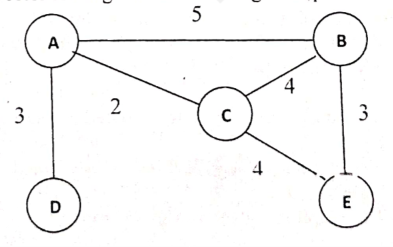20247m
Module 3: Network Layer & Routing
View this question on its own page →Explain the distance vector routing for the following example.
 Worked Solution
Distance vector routing: worked example
Network from the figure (link costs): A–B = 5, A–C = 2, A–D = 3, B–C = 4, B–E = 3, C–E = 4.
Principle
In distance vector routing each router keeps a table of the best-known distance to every destination and the next hop. Periodically it sends its vector (distance to all nodes) only to its direct neighbours. Each router then applies the Bellman-Ford equation:
Dₓ(y) = min over neighbours v of { c(x, v) + Dᵥ(y) }
The process repeats until no table changes (convergence).
Step 0: initial vectors (only direct neighbours known, ∞ = unknown)
Order: [A, B, C, D, E]
Router A B C D E A 0 5 2 3 ∞ B 5 0 4 ∞ 3 C 2 4 0 ∞ 4 D 3 ∞ ∞ 0 ∞ E ∞ 3 4 ∞ 0 Step 1: after the first exchange (using neighbours' initial vectors)
Example calculations:
- A → E: via B = 5 + 3 = 8; via C = 2 + 4 = 6; via D = 3 + ∞. Minimum = 6 (via C).
- B → D: via A = 5 + 3 = 8; via C = 4 + ∞; via E = 3 + ∞. Minimum = 8 (via A).
- C → D: via A = 2 + 3 = 5.
- D → B: via A = 3 + 5 = 8; D → C: via A = 3 + 2 = 5.
- E → A: via B = 3 + 5 = 8; via C = 4 + 2 = 6.
Router A B C D E A 0 5 2 3 6 B 5 0 4 8 3 C 2 4 0 5 4 D 3 8 5 0 ∞ E 6 3 4 ∞ 0 Step 2: after the second exchange
- D → E: via A = 3 + 6 = 9.
- E → D: via B = 3 + 8 = 11; via C = 4 + 5 = 9.
All other entries are unchanged.
Step 3: third exchange gives no change, so the tables have converged
Final routing tables (destination: cost via next hop)
Router To A To B To C To D To E A 0 5 (B) 2 (C) 3 (D) 6 (C) B 5 (A) 0 4 (C) 8 (A) 3 (E) C 2 (A) 4 (B) 0 5 (A) 4 (E) D 3 (A) 8 (A) 5 (A) 0 9 (A) E 6 (C) 3 (B) 4 (C) 9 (C) 0 Example: the best A→E path is A → C → E with cost 2 + 4 = 6. The best D→E path is D → A → C → E with cost 3 + 2 + 4 = 9.
Remarks
- Each router knows only its neighbours and their vectors, not the whole topology.
- Count-to-infinity: if a link fails, wrong information may circulate slowly; it is reduced with split horizon, poison reverse, and triggered updates.
- The protocol used in practice for this method is RIP.
- Install PocketlyBudget App•POCKETLY
Pocketly on Android
Log daily food, travel, and hostel expenses instantly. Set monthly spending limits and see where your money goes without complex spreadsheets.
Q7a. Explain how TCP provide a flow control service by using different variables.20247m
Module 4: Transport Layer & Congestion Control
View this question on its own page →Explain how TCP provide a flow control service by using different variables.
Worked SolutionTCP flow control
Flow control ensures the sender does not send data faster than the receiver can process it, so the receiver's buffer does not overflow. TCP uses a sliding window in which the receiver advertises how much free buffer space it has (the receive window, rwnd) in every segment's Window field (16 bits).
Variables used
At the receiver (connection has a receive buffer of size
RcvBuffer):Variable Meaning RcvBufferTotal size of the receive buffer LastByteRcvdNumber of the last byte that arrived from the network and was placed in the buffer LastByteReadNumber of the last byte the application has read from the buffer rwndFree space advertised to the sender Buffered data =
LastByteRcvd − LastByteRead≤RcvBuffer, sorwnd = RcvBuffer − (LastByteRcvd − LastByteRead)
The receiver puts the current
rwndin the window field of every ACK it sends.At the sender:
Variable Meaning LastByteSentLast byte sent LastByteAckedLast byte acknowledged rwndLatest window advertised by the receiver The sender keeps the amount of unacknowledged (in-flight) data within the advertised window:
LastByteSent − LastByteAcked ≤ rwnd
(In practice the limit is min(rwnd, cwnd), where cwnd is the congestion window.)
Working
- At connection setup,
rwnd = RcvBuffer. - The sender transmits up to
rwndbytes without waiting for ACKs. - As data arrives and the application reads it, the receiver updates
rwndand sends it back with each ACK. - If the application is slow, the buffer fills,
rwndshrinks, and the sender slows down. - When rwnd = 0, the sender stops. To avoid deadlock, it keeps sending 1-byte probe segments so the receiver can reply with a new
rwndonce buffer space becomes free. - When space opens, the receiver sends a window update and transmission resumes.
Example
RcvBuffer = 4000 bytes. Sender sends bytes 0–2999. Receiver has read 1000 bytes (LastByteRead = 999, LastByteRcvd = 2999):
rwnd = 4000 − (2999 − 999) = 2000. The sender may have at most 2000 unacknowledged bytes.
Silly window syndrome
Tiny window updates would cause tiny segments. It is avoided by Clark's solution (receiver advertises a window only when it has a useful amount of space free) and Nagle's algorithm (sender waits to combine small writes).
- At connection setup,
Q7b. Describe the various fields of UDP segment and also explain about UDP checksum with an example?20247m
Module 4: Transport Layer & Congestion Control
View this question on its own page →Describe the various fields of UDP segment and also explain about UDP checksum with an example?
Worked SolutionUDP segment format
UDP (User Datagram Protocol) is a connectionless, unreliable transport protocol with a very small 8-byte header:
 0                16                31
+-----------------+-----------------+
|  Source Port    | Destination Port|
|    (16 bits)    |    (16 bits)    |
+-----------------+-----------------+
|     Length      |    Checksum     |
|    (16 bits)    |    (16 bits)    |
+-----------------+-----------------+
|         Data (application)        |
+-----------------------------------+
Field Size Description Source port 16 bits Port of the sending process (optional; 0 if unused). Used as the reply address Destination port 16 bits Port of the receiving process (e.g. 53 = DNS, 67/68 = DHCP) Length 16 bits Length of the UDP header + data in bytes (minimum 8) Checksum 16 bits Error detection over the pseudo-header, UDP header and data Features: connectionless (no handshake), no acknowledgements, no retransmission, no flow or congestion control, preserves message boundaries, low overhead and fast. Used for DNS, DHCP, streaming, VoIP, online games, SNMP.
UDP checksum
The checksum is the 1's complement of the 1's complement sum of all 16-bit words of the pseudo-header (source IP, destination IP, zero byte, protocol = 17, UDP length), the UDP header (with the checksum field set to 0) and the data. If the total length is odd, the data is padded with a zero byte.
Sender's steps
- Divide the data into 16-bit words.
- Add all words using 1's complement addition (any carry out of the top bit is wrapped around and added back to the least significant bit).
- Complement the result (invert every bit). This is the checksum.
Receiver's steps
Add all the words including the checksum. If there is no error, the sum is 1111 1111 1111 1111. Any 0 bit means an error, and the datagram is discarded.
Example
Three 16-bit words:
Word 1 :  0110 0110 0110 0110   (0x6666)
Word 2 :  0101 0101 0101 0101   (0x5555)
Word 3 :  0000 1111 0000 1111   (0x0F0F)
Step 1: Word 1 + Word 2
  0110 0110 0110 0110
+ 0101 0101 0101 0101
= 1011 1011 1011 1011   (no carry)
Step 2: add Word 3
  1011 1011 1011 1011
+ 0000 1111 0000 1111
= 1100 1010 1100 1010   (0xCACA, no carry)
Step 3: 1's complement of the sum
Sum        = 1100 1010 1100 1010
Checksum   = 0011 0101 0011 0101   (0x3535)
Verification at the receiver: 0xCACA + 0x3535 = 0xFFFF =
1111 1111 1111 1111, so the data is accepted.Wrap-around example: 1111 1111 1111 1111 + 0000 0000 0000 0010 = 1 0000 0000 0000 0001; wrapping the carry gives 0000 0000 0000 0010.
Limitations: the checksum detects most single-bit and burst errors but cannot correct them, and two compensating errors can go undetected. In IPv4 the checksum is optional (0 means "not computed"); in IPv6 it is mandatory.
Q8a. Describe a TCP connection. Explain a TCP connection establishment and Connection Release using three way handshaking.20247m
Module 4: Transport Layer & Congestion Control
View this question on its own page →Describe a TCP connection. Explain a TCP connection establishment and Connection Release using three way handshaking.
Worked SolutionTCP connection
TCP (Transmission Control Protocol) is a connection-oriented, reliable, byte-stream transport protocol. A logical connection is set up between two processes before data transfer and closed afterwards.
Features of a TCP connection:
- Identified by a socket pair: (source IP, source port, destination IP, destination port).
- Full duplex: data flows in both directions at once.
- Point-to-point: exactly two endpoints (no multicast).
- Reliable: sequence numbers, acknowledgements, retransmission, checksum.
- Byte stream: every byte is numbered; the application data has no message boundaries.
- Provides flow control (sliding window) and congestion control.
Three phases: connection establishment → data transfer → connection release.
Connection establishment: three-way handshake
Client Server | | (server does passive open: LISTEN) |-- 1. SYN, seq = x ------------------->| active open | | |<-- 2. SYN + ACK, seq = y, ack = x+1 ---| | | |-- 3. ACK, seq = x+1, ack = y+1 ------->| | connection ESTABLISHED |- SYN: the client sends a segment with the SYN flag set and an initial sequence number x (random). It enters SYN-SENT.
- SYN + ACK: the server replies with SYN and ACK set, its own initial sequence number y, and ack = x + 1. It enters SYN-RECEIVED.
- ACK: the client acknowledges with ack = y + 1. Both sides are now ESTABLISHED and data can flow.
The SYN segment consumes one sequence number. The handshake synchronises sequence numbers and agrees on parameters (window size, MSS).
Why three steps? Two steps could not confirm that the client received the server's initial sequence number, and old duplicate SYNs could create false connections. SYN flooding (many half-open connections) is a known attack, mitigated with SYN cookies.
Connection release
Each direction is closed separately. The common four-segment exchange is FIN, ACK, FIN, ACK. When the server has no more data, it can combine its ACK and FIN into one segment, which gives the three-way release asked for here.
Client Server |-- 1. FIN, seq = u ------------------->| client done sending |<-- 2. FIN + ACK, seq = v, ack = u+1 ---| server acknowledges and also closes |-- 3. ACK, ack = v+1 ------------------>| | client waits 2×MSL (TIME_WAIT), then closed- FIN: the side that finishes (client) sends a segment with the FIN flag.
- FIN + ACK: the server acknowledges it (ack = u + 1) and, having no more data, sets FIN in the same segment.
- ACK: the client acknowledges the server's FIN. The server closes when it receives this ACK.
The client stays in TIME_WAIT for 2 × MSL (maximum segment lifetime) so that a lost final ACK can be resent and old segments expire.
Four-way variant: if the server still has data to send after receiving the FIN, it sends a plain ACK first (half-close), later sends its own FIN, and the client sends the last ACK. An abrupt close can also be done with an RST segment.
Q8b. What is congestion? Explain three congestion control policies in Transport Layer with suitable diagram?20247m
Module 4: Transport Layer & Congestion Control
View this question on its own page →What is congestion? Explain three congestion control policies in Transport Layer with suitable diagram?
Worked SolutionCongestion
Congestion occurs when the load offered to a network (or part of it) exceeds its capacity, so routers' buffers fill up, delay increases and packets are dropped. Lost packets are retransmitted, adding even more load, and throughput can collapse (congestion collapse).
Throughput
   |        ____________
   |      /             \___   <- beyond capacity: packets dropped,
   |     /                    \    throughput falls
   |    /
   +---------------------------- Offered load
        (no congestion)  (congestion)
Causes: limited router buffers and link bandwidth, slow processors, many senders sending bursts, retransmissions of lost packets.
Difference from flow control: flow control is between one sender and one receiver; congestion control is a global issue involving all hosts and routers.
TCP controls congestion by using a congestion window (cwnd) in addition to the receiver's window: the sender may have at most min(rwnd, cwnd) bytes unacknowledged. The window is managed with three policies (phases).
Three congestion control policies in TCP
1. Slow start (exponential increase)
- Starts with cwnd = 1 MSS.
- For every ACK received, cwnd increases by 1 MSS, so cwnd doubles every RTT (1, 2, 4, 8, ...).
- Continues until cwnd reaches the slow-start threshold (ssthresh), then switches to congestion avoidance.
2. Congestion avoidance (additive increase)
- When cwnd ≥ ssthresh, cwnd grows linearly: +1 MSS per RTT (each ACK adds MSS²/cwnd).
- This probes for extra bandwidth carefully, avoiding congestion.
3. Congestion detection (multiplicative decrease)
Congestion is detected by packet loss:
Event Meaning Reaction (TCP Tahoe / Reno) Timeout Strong congestion ssthresh = cwnd / 2; cwnd = 1 MSS; restart slow start 3 duplicate ACKs Mild congestion (some segments still get through) Fast retransmit of the lost segment; Reno: ssthresh = cwnd / 2; cwnd = ssthresh (fast recovery) and continue with congestion avoidance Together these implement AIMD (Additive Increase, Multiplicative Decrease).
Diagram: cwnd versus time
Initial ssthresh = 8 MSS. A timeout occurs when cwnd = 12 (after RTT 8), so ssthresh becomes 6 and cwnd drops to 1.
cwnd (MSS)
 12 |                      *
 11 |                   *
 10 |                *
  9 |             *
  8 |          *                             *   <- ssthresh = 8, later 6
  7 |                                     *
  6 |                                  *
  5 |
  4 |       *                       *
  3 |
  2 |    *                       *
  1 | *                       *
    +------------------------------------------
      1  2  3  4  5  6  7  8  9 10 11 12 13 14   RTT
RTT 1 2 3 4 5 6 7 8 9 10 11 12 13 14 cwnd 1 2 4 8 9 10 11 12 1 2 4 6 7 8 Phase slow start (exponential) reaches ssthresh congestion avoidance (linear) timeout slow start reaches new ssthresh = 6 congestion avoidance Summary
Phase Increase Trigger Slow start Exponential (×2 per RTT) Start, or after a timeout; until ssthresh Congestion avoidance Linear (+1 MSS per RTT) cwnd ≥ ssthresh Congestion detection Multiplicative decrease Timeout or 3 duplicate ACKs (Other techniques in the network layer include traffic shaping with leaky and token buckets, load shedding, and RED.)
Q9a. Explain recursive resolution and iterative resolution in name address resolution.20247m
Module 5: Application Layer & Security
View this question on its own page →Explain recursive resolution and iterative resolution in name address resolution.
Worked SolutionName-address resolution in DNS
A client (the resolver) must convert a domain name such as
www.example.cominto an IP address. DNS is a hierarchical, distributed database of servers: root servers → TLD servers (.com) → authoritative servers (example.com), plus a local (recursive) DNS server of the ISP or organisation. The lookup can be done in two ways.1. Recursive resolution
The client asks a DNS server to do the entire job. If that server does not know the answer, it contacts other servers on the client's behalf and returns only the final answer (or an error).
Client -> Local DNS: "IP of www.example.com?"
           Local DNS -> Root -> TLD -> Authoritative (chain)
           <- final IP address
Client <- Local DNS: 93.184.216.34
Characteristics:
- Burden is on the queried server; the client sends one query and gets one answer.
- The server usually caches the result, speeding up later queries.
- Client-to-local-server queries are normally recursive.
2. Iterative resolution
The client (or the local server) asks a server, and if the server cannot answer it returns a referral: the address of another server that is closer to the answer. The asker then queries that next server itself, repeating until the answer is found.
Local DNS -> Root server:  "www.example.com?"
          <- referral: ask the .com TLD server
Local DNS -> TLD server:   "www.example.com?"
          <- referral: ask ns1.example.com
Local DNS -> Authoritative: "www.example.com?"
          <- 93.184.216.34
Characteristics:
- Burden is on the requester; each server does minimal work.
- Servers reply immediately with the best information they have.
- Root and TLD servers normally answer only iteratively (to protect them from overload).
Comparison
Basis Recursive Iterative Who does the work The queried server resolves fully The requester follows referrals itself Reply to the requester Final answer (or error) Answer or a referral to another server Load on the server High Low Number of queries by the client One Several Typical use Client → local DNS server Local DNS server → root / TLD / authoritative servers Caching benefit Server caches the final answers Requester caches each step In practice the two are combined: the host sends a recursive query to its local DNS server, which then performs iterative queries against the root, TLD, and authoritative servers and returns the final IP address to the host.
Q9b. Differentiate between SMTP and POP protocols? Explain Mail Access Agents in detail?20247m
Module 5: Application Layer & Security
View this question on its own page →Differentiate between SMTP and POP protocols? Explain Mail Access Agents in detail?
Worked SolutionEmail architecture (context)
Email uses three kinds of agents:
- UA (User Agent): the mail client (Outlook, Thunderbird, Gmail app) used to compose and read mail.
- MTA (Message Transfer Agent): the server software that transfers mail between servers; it uses SMTP.
- MAA (Message Access Agent): lets the recipient retrieve mail from the mailbox server; it uses POP3 or IMAP4.
Sender UA --SMTP--> Sender's MTA --SMTP--> Receiver's MTA --> Mailbox
                                                                 |
Receiver UA <------------- POP3 / IMAP4 (MAA) -------------------+
SMTP vs POP
Basis SMTP (Simple Mail Transfer Protocol) POP3 (Post Office Protocol v3) Purpose Sending / transferring mail Retrieving mail from the server Type Push protocol Pull protocol Direction Client → server, and server → server Server → client Used by MTA (sender UA to server, between servers) MAA (receiver UA) Port 25 (587 for submission; 465 secure) 110 (995 with SSL/TLS) Commands HELO/EHLO, MAIL FROM, RCPT TO, DATA, QUIT USER, PASS, STAT, LIST, RETR, DELE, QUIT Message storage Only relays it toward the destination Downloads to the local machine, usually deleting it from the server Format handling Transfers 7-bit ASCII (binary content via MIME) Retrieves the stored message Connection TCP, persistent for multiple messages TCP, one session per download Mail Access Agents (MAA)
SMTP only pushes mail to the receiver's mail server. Because the recipient's computer is often not always online, the message is stored in the mailbox on the server, and the user's UA fetches it later with a Mail Access Agent. MAAs are pull protocols.
1. POP3 (Post Office Protocol, version 3)
- Simple protocol with three phases: authorization (USER, PASS), transaction (STAT, LIST, RETR, DELE), and update (QUIT applies deletions).
- Two modes: delete mode (messages removed from the server after download) and keep mode (copies remain on the server).
- Advantages: simple, quick, works offline after download, saves server space.
- Disadvantages: poor for several devices (mail lives on one computer), no server-side folders, limited management on the server.
2. IMAP4 (Internet Message Access Protocol, version 4)
- More powerful: mail stays on the server, and the client works on it remotely.
- Features: create, delete, and rename server-side mailboxes/folders; partial download (read headers only, or part of a message); search on the server; flags (read, replied, deleted) synchronised across devices; multiple clients see the same mailbox.
- Port 143 (993 with SSL/TLS).
- Disadvantages: needs more server storage and resources and a continuous connection for full use.
3. Web-based mail (HTTP)
- Gmail, Yahoo, or Outlook.com: the user reads mail through a browser over HTTP/HTTPS; the web server acts as the MAA using POP3/IMAP internally. Mail is sent from the browser to the mail server by HTTP, then between servers by SMTP.
POP3 vs IMAP4
Basis POP3 IMAP4 Mail location Downloaded to the client Kept on the server Multi-device use Poor Excellent Server-side folders No Yes Partial fetch / search No Yes Complexity and server load Low Higher Summary: SMTP is used to send mail; POP3 and IMAP4 (the Mail Access Agents) are used to read mail.
PYQDeck for Android
Solve BEU previous-year exam papers anywhere, anytime. Fast search, offline paper viewing, and step-by-step solutions designed specifically for your phone.