
Computer Networks
100602Module 3: Network Layer & Routing
Q1a. An Internet Service Provider (ISP) has the following chunk of CIDR-based IP addresses available with it: 245.248.128.0/20 The ISP wants to give half of this chunk of addresses to organization A, and a quarter to organization B, while retaining the remaining with itself. Which of the following is a valid allocation of addresses to A and B? (i) 245.248.136.0/21 and 245.248.128.0/22 (ii) 245.248.128.0/21 and 245.248.128.0/22 (iii) 245.248.132.0/22 and 245.248.132.0/21 (iv) 245.248.136.0/22 and 245.248.132.0/2120202m
Module 3: Network Layer & Routing
View this question on its own page →An Internet Service Provider (ISP) has the following chunk of CIDR-based IP addresses available with it:
245.248.128.0/20
The ISP wants to give half of this chunk of addresses to organization A, and a quarter to organization B, while retaining the remaining with itself. Which of the following is a valid allocation of addresses to A and B?
(i) 245.248.136.0/21 and 245.248.128.0/22
(ii) 245.248.128.0/21 and 245.248.128.0/22
(iii) 245.248.132.0/22 and 245.248.132.0/21
(iv) 245.248.136.0/22 and 245.248.132.0/21Worked SolutionAnswer: (i) 245.248.136.0/21 and 245.248.128.0/22
Why: The block 245.248.128.0/20 spans 245.248.128.0 – 245.248.143.255 (4096 addresses), so a half is a /21 (2048 addrs) and a quarter is a /22 (1024 addrs). Option (i) gives A the upper half 136.0 – 143.255 and B the first quarter 128.0 – 131.255: both lie inside the /20 and do not overlap. In (ii) both start at 128.0, so B's /22 is nested inside A's /21 (overlap); in (iii) the sizes are swapped (A gets only 1024) and they overlap; in (iv) A gets a /22 (a quarter, not a half) and overlaps B's /21.
Q1a. Network layer of OSI model does not establish any relationship among different packets of same message. (Write True or False)20152m
Module 3: Network Layer & Routing
View this question on its own page →Network layer of OSI model does not establish any relationship among different packets of same message. (Write True or False)
Worked SolutionTrue.
Why: The network layer provides connectionless (datagram) service in IP — each packet is routed independently and carries no binding to other packets of the same message. Relationships among segments of one message (ordering, sequencing, reassembly) are maintained by the transport layer (e.g., TCP), not by the network layer. (Only connection-oriented network layers such as ATM/legacy X.25 establish such relationships.)
Q1c. Internetworking protocol is known as (i) TCP (ii) IP (iii) ISP (iv) TCP/IP20212m
Module 3: Network Layer & Routing
View this question on its own page →Internetworking protocol is known as
(i) TCP
(ii) IP
(iii) ISP
(iv) TCP/IPWorked SolutionAnswer: (ii) IP
Why: IP (Internet Protocol) is the network-layer protocol that delivers packets hop-by-hop across interconnected networks using logical addresses — that is exactly what "internetworking" means. TCP is only a transport-layer protocol, an ISP is an organisation that provides connectivity (not a protocol), and TCP/IP is the name of the entire protocol suite rather than one single protocol.
Q1c. Which of the following is not applicable for IP? (i) Error reporting (ii) Handle addressing conventions (iii) Datagram format (iv) Packet handling conventions20192m
Module 3: Network Layer & Routing
View this question on its own page →Which of the following is not applicable for IP?
(i) Error reporting
(ii) Handle addressing conventions
(iii) Datagram format
(iv) Packet handling conventionsWorked SolutionAnswer: (i) Error reporting
Why: IP is a connectionless, best-effort service that only handles addressing conventions (source/destination address fields), the datagram format, and packet-handling conventions such as fragmentation, TTL and reassembly. Error reporting and diagnostic notification are done by ICMP, which sits on top of IP, so it is not an IP function.
Q1c. Which of the following is not applicable for IP? (i) Error reporting (ii) Handle addressing conventions (iii) Datagram format (iv) Packet handling conventions20182m
Module 3: Network Layer & Routing
View this question on its own page →Which of the following is not applicable for IP?
(i) Error reporting
(ii) Handle addressing conventions
(iii) Datagram format
(iv) Packet handling conventionsWorked SolutionAnswer: (i) Error reporting
Why: IP itself performs only best-effort delivery — it defines the datagram format, handles addressing conventions (classful/CIDR addressing) and packet handling conventions (fragmentation, TTL, options), but error reporting is not done by IP; it is the job of the companion protocol ICMP, which carries error and control messages (destination unreachable, time exceeded, echo, etc.) inside IP datagrams.
Q1c. In specific, if the systems use separate protocols, which one of the following devices is used to link two systems? (i) Repeater (ii) Gateway (iii) Bridge (iv) Hub20242m
Module 3: Network Layer & Routing
View this question on its own page →In specific, if the systems use separate protocols, which one of the following devices is used to link two systems?
(i) Repeater
(ii) Gateway
(iii) Bridge
(iv) HubWorked SolutionCorrect answer: (ii) Gateway
A gateway connects networks or systems that use different protocols and can translate between those protocols, allowing otherwise incompatible systems to communicate.
- Repeater: Operates at the physical layer and regenerates signals; it does not translate protocols.
- Bridge: Operates at the data-link layer and forwards frames between LAN segments using compatible link-layer protocols.
- Hub: A multiport repeater that sends incoming bits to its other ports; it does not perform protocol translation.
Exam tip: When a question specifically says that two systems use different protocols, the expected answer is generally Gateway.
Q1d. Which device uses logical addressing system? (i) Hub (ii) Switch (iii) Bridge (iv) Router20212m
Module 3: Network Layer & Routing
View this question on its own page →Which device uses logical addressing system?
(i) Hub
(ii) Switch
(iii) Bridge
(iv) RouterWorked SolutionAnswer: (iv) Router
Why: A router works at the network layer and forwards packets using logical (IP) addresses, which are hierarchical and routable across networks. A hub is a Layer-1 repeater that simply broadcasts signals and performs no addressing, while a switch and a bridge are Layer-2 devices that forward frames using physical (MAC) addresses — so none of them uses logical addressing.
Q1d. Which the following is an inter-domain routing protocol? (i) RIP (ii) OSPF (iii) BGP (iv) Both (a) & (b)20232m
Module 3: Network Layer & Routing
View this question on its own page →Which the following is an inter-domain routing protocol?
(i) RIP
(ii) OSPF
(iii) BGP
(iv) Both (a) & (b)Worked SolutionAnswer: (iii) BGP
BGP (Border Gateway Protocol) is the inter-domain (exterior) routing protocol that exchanges routes between autonomous systems on the Internet. RIP and OSPF are intra-domain (interior) protocols that work inside one AS, so option (iv) is wrong.
Q1d. What is the maximum header size of an IP packet? (i) 32 bytes (ii) 64 bytes (iii) 30 bytes (iv) 60 bytes20222m
Module 3: Network Layer & Routing
View this question on its own page →What is the maximum header size of an IP packet?
(i) 32 bytes
(ii) 64 bytes
(iii) 30 bytes
(iv) 60 bytesWorked SolutionAnswer: (iv) 60 bytes
Why: The IPv4 header length field (IHL) is 4 bits, giving words of 4 bytes = bytes total header, i.e. a maximum header size of 60 bytes (the minimum is 20 bytes with no options). 32/64/30 bytes do not correspond to any IHL-derived value; 64 would be the header limit only under protocols like IPv6's usual 40-byte base + extensions pattern.
Q1d. Which one of the following is not a function of network layer? (i) Routing (ii) Inter-networking (iii) Congestion control (iv) None of the above20192m
Module 3: Network Layer & Routing
View this question on its own page →Which one of the following is not a function of network layer?
(i) Routing
(ii) Inter-networking
(iii) Congestion control
(iv) None of the aboveWorked SolutionAnswer: (iv) None of the above
Why: Routing (choosing the best path), inter-networking (delivering a packet across multiple interconnected networks) and congestion control (regulating traffic so buffers/queues do not overflow) are all recognised functions of the network layer. Since options (i), (ii) and (iii) are each genuine network-layer functions, none of them is a "non-function", making (iv) the correct choice.
- Install PocketlyBudget App•POCKETLY
Pocketly on Android
Log daily food, travel, and hostel expenses instantly. Set monthly spending limits and see where your money goes without complex spreadsheets.
Q1e. Which of the following is correct IPv4 address? (i) 124.201.3.1.52 (ii) 300.142.210.64 (iii) 01.200.128.123 (iv) 128.64.0.020242m
Module 3: Network Layer & Routing
View this question on its own page →Which of the following is correct IPv4 address?
(i) 124.201.3.1.52
(ii) 300.142.210.64
(iii) 01.200.128.123
(iv) 128.64.0.0Worked SolutionAnswer: (iv) 128.64.0.0
A valid dotted-decimal IPv4 address has exactly four octets separated by three dots, every octet in the range 0-255, and no leading zeros (a leading zero would be read as octal).
- (i)
124.201.3.1.52has five octets, so it is not a 32-bit dotted-decimal address. - (ii)
300.142.210.64contains the value 300, which exceeds 255. - (iii)
01.200.128.123begins with a leading zero, which is invalid/ambiguous. - (iv)
128.64.0.0has four octets, each within 0-255, so it is a legal IPv4 address (it is also a Class B address).
- (i)
Q1e. What is flooding in routing?20152m
Module 3: Network Layer & Routing
View this question on its own page →What is flooding in routing?
Worked SolutionFlooding is a simple routing/forwarding technique in which every router, on receiving a packet, sends a copy of it out on every outgoing line except the one on which it arrived.
- The packet spreads through the entire network like a wave, so if any path exists between source and destination, the packet is guaranteed to be delivered — it is highly robust against link/router failures.
- To stop infinite circulation, a hop counter (sequence number) is decremented at each hop, and duplicate packets are discarded by remembering (packet id, port).
- Drawbacks: heavy traffic congestion and duplicate packets; used mainly for broadcast, for broadcasting management/trap messages, or as a fallback during network failures.
Q1f. Which one of the following protocols is NOT used to resolve one form of address to another one? (i) DNS (ii) ARP (iii) DHCP (iv) RARP20162m
Module 3: Network Layer & Routing
View this question on its own page →Which one of the following protocols is NOT used to resolve one form of address to another one?
(i) DNS
(ii) ARP
(iii) DHCP
(iv) RARPWorked SolutionAnswer: (iii) DHCP
Why: DNS resolves a domain name to an IP address, ARP resolves an IP address to a MAC address, and RARP resolves a MAC address to an IP address — each maps one address form to another. DHCP instead dynamically assigns/leases an IP address and configuration parameters (subnet mask, default gateway, DNS server) to a host; it does not translate one address form into another.
Q1f. The checksum in IP must be recomputed at every router because of change in ____ fields. (i) TTL, Options, Identification Number, Offset (ii) TTL, Options, Data, Offset (iii) TTL, Options, Datagram Length, Offset (iv) TTL, Header Length, Offset, ToS20242m
Module 3: Network Layer & Routing
View this question on its own page →The checksum in IP must be recomputed at every router because of change in ____ fields.
(i) TTL, Options, Identification Number, Offset
(ii) TTL, Options, Data, Offset
(iii) TTL, Options, Datagram Length, Offset
(iv) TTL, Header Length, Offset, ToSWorked SolutionAnswer: (iii) TTL, Options, Datagram Length, Offset
The IP header checksum is computed over the IP header only (the payload is excluded), so any change to a header field invalidates the stored checksum. A router always decrements the TTL field before forwarding, which by itself forces recomputation. The Options fields (record route, timestamp, etc.) may be updated by routers along the path. If the router must fragment the datagram, every fragment gets a new datagram (total) length and a new fragment offset, so each new header needs a fresh checksum.
The data (ii) is not covered by the header checksum, so it can never trigger recomputation. The identification number (i) is copied unchanged from the parent datagram into each fragment - its job is to tie the fragments together - so it does not change during forwarding. Header length and ToS (iv) are also not rewritten by a normal forwarding router, so they are not the reason for per-hop recomputation.
Q1f. Which one of the following is a valid host for network 192.168.4.32/68? (i) 192.168.4.39 (ii) 192.168.4.50 (iii) 192.168.4.47 (iv) 192.168.4.3120232m
Module 3: Network Layer & Routing
View this question on its own page →Which one of the following is a valid host for network 192.168.4.32/68?
(i) 192.168.4.39
(ii) 192.168.4.50
(iii) 192.168.4.47
(iv) 192.168.4.31Worked SolutionAnswer: (i) 192.168.4.39
The prefix
/68is not possible for IPv4 (the maximum is /32). The question most likely means 192.168.4.32/28, so that is what is solved here.For /28: block size = 2^(32−28) = 16 addresses.
- Network address: 192.168.4.32
- Broadcast address: 192.168.4.47
- Valid host range: 192.168.4.33 – 192.168.4.46
Option Address Status (i) 192.168.4.39 Valid host (ii) 192.168.4.50 Belongs to the next block (.48–.63) (iii) 192.168.4.47 Broadcast address, not usable (iv) 192.168.4.31 Belongs to the previous block (.16–.31) Q1f. What is the default subnet mask for a class A network? (i) 127.0.0.1 (ii) 255.0.0.0 (iii) 255.255.255.0 (iv) 255.255.255.020202m
Module 3: Network Layer & Routing
View this question on its own page →What is the default subnet mask for a class A network?
(i) 127.0.0.1
(ii) 255.0.0.0
(iii) 255.255.255.0
(iv) 255.255.255.0Worked SolutionAnswer: (ii) 255.0.0.0
Why: Class A uses the first 8 bits as the network id (first octet 1–126), so the default mask is i.e. /8, leaving 24 bits for hosts ( hosts). Option (i) 127.0.0.1 is the loopback address, not a mask, and (iii)/(iv) 255.255.255.0 (/24) is the class C default mask.
Q1g. Which of the following statements could be valid with respect to the ICMP (Internet Control Message Protocol)? (i) It reports all errors which occur during transmission. (ii) A redirect message is used when a router notices that a packet seems to have been routed wrongly. (iii) It informs routers when an incorrect path has been taken. (iv) The "destination unreachable" type message is used when a router cannot locate the destination.20242m
Module 3: Network Layer & Routing
View this question on its own page →Which of the following statements could be valid with respect to the ICMP (Internet Control Message Protocol)?
(i) It reports all errors which occur during transmission.
(ii) A redirect message is used when a router notices that a packet seems to have been routed wrongly.
(iii) It informs routers when an incorrect path has been taken.
(iv) The "destination unreachable" type message is used when a router cannot locate the destination.Worked SolutionAnswer: (ii)
ICMP Redirect (type 5) is sent by a router to the original source host when it forwards a datagram and finds that the next hop it used is not the best router for that destination - in other words, the packet appears to have been routed wrongly and the host should use a different router for subsequent packets to that destination. Statement (ii) describes exactly this.
The other statements are not valid: (i) is false because ICMP does not report every transmission error - it reports datagram-handling problems (destination unreachable, time exceeded, parameter problem, etc.), and by design it never reports an error contained inside an ICMP error message itself. (iii) misstates the recipient: redirect messages go to the sending host, not to routers, and routers must not alter their routing tables from redirects. (iv) misstates the trigger: Destination Unreachable (type 3) means the datagram could not be delivered - network unreachable, host unreachable, protocol unreachable, port unreachable, fragmentation needed - and it is generated by end hosts as well as routers, so it is not simply the case of a router being unable to locate the destination.
Q1g. What does the term 'best effort' mean in context with IP?20172m
Module 3: Network Layer & Routing
View this question on its own page →What does the term 'best effort' mean in context with IP?
Worked SolutionBest effort means IP makes no guarantees about delivery — it will try its utmost to deliver each datagram, but if something goes wrong (congestion, no route, TTL expiry, corruption) the packet is silently dropped, with no notification to the sender and no retransmission by IP itself.
- IP provides: connectionless, unordered, unreliable delivery with no duplicate protection, no flow/congestion control and no error recovery — only header checksum for basic corruption detection.
- Any required reliability (retransmission, ordering, flow control) must be added by upper layers (TCP/UDP at the transport layer, or the application).
- This keeps the network core simple and scalable ("smart edges, dumb core"), which is the fundamental design philosophy of the Internet.
Q1h. The protocol that maps a physical (MAC) address to the corresponding logical address is (i) ARP (ii) RARP (iii) ICMP (iv) IMAP420232m
Module 3: Network Layer & Routing
View this question on its own page →The protocol that maps a physical (MAC) address to the corresponding logical address is
(i) ARP
(ii) RARP
(iii) ICMP
(iv) IMAP4Worked SolutionAnswer: (ii) RARP
- RARP (Reverse Address Resolution Protocol) maps a physical (MAC) address to a logical (IP) address. A diskless host that knows only its MAC address uses it to ask a RARP server for its IP address.
- ARP does the opposite: it maps a logical (IP) address to a physical (MAC) address.
- ICMP reports errors and control messages, and IMAP4 is a mail access protocol.
(RARP has been superseded by BOOTP and DHCP.)
Q1i. Which one of the following is TRUE interior Gateway routing protocols - Routing Information protocol (RIP) and Open Shortest Path First (OSPF)? (i) RIP uses distance vector routing and OSPF uses link state routing (ii) OSPF uses distance vector routing and RIP uses link state routing (iii) Both RIP and OSPF use link state routing (iv) Both RIP and OSPF use distance vector routing20162m
Module 3: Network Layer & Routing
View this question on its own page →Which one of the following is TRUE interior Gateway routing protocols - Routing Information protocol (RIP) and Open Shortest Path First (OSPF)?
(i) RIP uses distance vector routing and OSPF uses link state routing
(ii) OSPF uses distance vector routing and RIP uses link state routing
(iii) Both RIP and OSPF use link state routing
(iv) Both RIP and OSPF use distance vector routingWorked SolutionAnswer: (i) RIP uses distance vector routing and OSPF uses link state routing
Why: RIP periodically exchanges entire routing tables with its neighbours and selects paths by hop count (Bellman-Ford / distance-vector algorithm), whereas OSPF floods link-state advertisements so every router builds a common topology map and runs Dijkstra's SPF algorithm to compute least-cost paths.
- Install PocketlyBudget App•POCKETLY
Pocketly on Android
Log daily food, travel, and hostel expenses instantly. Set monthly spending limits and see where your money goes without complex spreadsheets.
Q2b. Explain Datagram Approach and Virtual Circuit Approach with suitable diagram?20247m
Module 3: Network Layer & Routing
View this question on its own page →Explain Datagram Approach and Virtual Circuit Approach with suitable diagram?
Worked SolutionDatagram Approach and Virtual-Circuit Approach
Definition: Packet-switched networks can deliver packets using either a datagram (connectionless) approach or a virtual-circuit (connection-oriented) approach.
1. Datagram approach
Each packet is treated independently. No connection setup is required, each packet carries the destination address, and routers make forwarding decisions packet by packet. Packets may take different routes and may arrive out of order.
MermaidDiagramRendering diagram…- Setup: Not required.
- Routing: Decided independently for each packet.
- Addressing: Full destination address in each packet.
- Router state: No per-connection virtual-circuit state.
- Ordering: Not guaranteed.
- Example: IP networks use datagram packet delivery.
2. Virtual-circuit approach
A logical path is established before data transfer. Routers keep forwarding-table entries, and packets carry a virtual-circuit identifier (VCI). Packets normally follow the established path; the connection is released when communication ends.
MermaidDiagramRendering diagram…Phases:
- Setup: Choose a path and install forwarding entries at the routers.
- Data transfer: Forward packets using the VCI and established path.
- Teardown: Remove the virtual-circuit entries and release resources.
Comparison
Aspect Datagram Virtual circuit Connection setup Not required Required Routing Per packet Path established before transfer Packet header Full destination address VCI/label Router state No per-connection VC state Per-connection forwarding state Packet order May be out of order Usually maintained along the path Failure handling Packets may be rerouted Circuit may need re-establishment Examples IP datagram delivery X.25, ATM; MPLS uses label-switched paths Conclusion: Datagram delivery offers flexibility without connection setup. Virtual circuits require setup and router state but provide a logical path and simpler per-packet identifiers.
Q3a. The address of a class B host is to be split into subnets with a 6-bit subnet number: What is the maximum number of subnets and the maximum number of hosts in each subnet? What is the number of networks allowed under Class B addresses?20167m
Module 3: Network Layer & Routing
View this question on its own page →The address of a class B host is to be split into subnets with a 6-bit subnet number: What is the maximum number of subnets and the maximum number of hosts in each subnet? What is the number of networks allowed under Class B addresses?
Worked SolutionSubnetting a Class B Address with a 6-bit Subnet Field
Given: the address of a Class B host is to be divided into subnets using a 6-bit subnet number.
A classful Class B address has 16 network bits and 16 host bits:
| network id : 16 bits | host id : 16 bits |
| network id : 16 bits | subnet : 6 bits | host : 16 - 6 = 10 bits |
1. Maximum number of subnets
Subnet bits are borrowed from the host id, so
(If the all-zeros subnet and the all-ones subnet are not usable, as in the old classful rules, only subnets are usable, but the maximum count is .)
2. Maximum number of hosts in each subnet
Host bits left after borrowing 6 bits:
The subtraction of 2 removes the subnet's network address (all host bits 0) and its broadcast address (all host bits 1).
3. Number of networks allowed under Class B addresses
Class B reserves a 2-bit class prefix (
10), leaving a 14-bit network id:Final answers: maximum subnets = 64, maximum hosts per subnet = 1022, number of Class B networks = 16384.
Q3a. We know that there are 2 types of address schemes (i.e. IP address and MAC address) in computer networks. Explain what the need of having two types of addresses. What will happen if we use only IP address in computer networks?201914m
Module 3: Network Layer & Routing
View this question on its own page →We know that there are 2 types of address schemes (i.e. IP address and MAC address) in computer networks. Explain what the need of having two types of addresses. What will happen if we use only IP address in computer networks?
Worked SolutionNeed for Two Address Schemes: IP Address vs MAC Address
A host reachable on a network needs two fundamentally different kinds of identification: a logical (software-assigned) address for locating it across the whole internet and a physical (hardware-burned) address for delivering a frame to the correct interface on the local link. The network layer uses the IP address; the data link layer uses the MAC address. They solve different problems at different scopes, and neither can replace the other.
1. What each address is
Property IP address (logical) MAC address (physical) Assigned by Network administrator / DHCP, by software Manufacturer, burned into NIC ROM Scope Global — meaningful across the entire internetwork Local — meaningful only within the LAN segment Structure Network part + host part (hierarchical, e.g. /24) Flat, no hierarchy: 48-bit OUI + device ID Changes when Host moves to another network Never (fixed to the NIC) Layer Network layer (L3) Data link layer (L2) Delivery goal Find a route to the destination network Deliver the frame to one interface on the link 2. Why both are required
- Hierarchy vs flat identification. Routing tables would explode if every one of billions of devices had its own globally-routable entry. IP addresses are hierarchical (network + host), so a router only stores network-level routes. MAC addresses are flat and unique but carry no topological information, so they cannot be used for global routing.
- Separation of duties across layers. IP addresses are used end-to-end, from source host to destination host, by routers along the path. MAC addresses are used hop-to-hop: each router strips the incoming frame and re-frames the packet with the MAC addresses of the next hop. This layering keeps L2 LAN technologies (Ethernet, Wi-Fi) independent of L3 internetworking.
- Interoperability of heterogeneous networks. An IP datagram can cross Ethernet, token ring, ATM or Wi-Fi links because the logical address stays constant while the link-layer (MAC) address is rewritten at every hop.
- Dynamic reconfiguration. A laptop moving from Wi-Fi to Ethernet keeps its IP configuration (via DHCP) but gets a new link-layer context; the ARP mechanism binds the stable logical address to the current physical one on demand.
3. What happens if only the IP address is used
- No local delivery mechanism. IP alone cannot put bits on a wire; frames need a MAC (or equivalent) address to be accepted by a NIC, so the last hop of delivery would be impossible.
- Every device must store a global routing table. With a flat, non-hierarchical scheme each node would need an entry for all other nodes — state per device for hosts, infeasible at internet scale.
- Broadcast storm / scanning problem. Locating a host would require broadcasting to every device on every network, wasting bandwidth and destroying scalability.
- Loss of technology independence. LAN hardware would have to understand IP directly, tightly coupling L2 and L3 and making new link technologies impossible to add transparently.
- No bootstrapping. At power-on a host knows its own MAC but not yet its IP; protocols like ARP map IP → MAC precisely because both addresses must coexist.
Conclusion: the IP address answers "which network is the destination on, and how do I route there?", while the MAC address answers "which interface on this link should receive the frame?". Both are indispensable for scalable, layered, technology-independent communication.
Q4a. In an IPv4 datagram, the M bit is 0, the value of HLEN is 10, the value of total length is 400 and the fragment offset value is 300. Find the position of the datagram, the sequence numbers of the first and the last bytes of the payload respectively.20167m
Module 3: Network Layer & Routing
View this question on its own page →In an IPv4 datagram, the M bit is 0, the value of HLEN is 10, the value of total length is 400 and the fragment offset value is 300. Find the position of the datagram, the sequence numbers of the first and the last bytes of the payload respectively.
Worked SolutionIPv4 Fragment: Position and Payload Byte Numbers
Given: M bit = 0, HLEN = 10, Total Length = 400, Fragment Offset = 300.
Step 1: Header size
HLEN is counted in 32-bit (4-byte) words:
Step 2: Payload carried by this fragment
Step 3: Position of the fragment in the original datagram
The Fragment Offset field is expressed in units of 8 bytes:
So the payload of this datagram begins at byte 2400 of the original datagram's data field.
Step 4: Interpretation of M = 0
M = 0 (no more fragments) means this is the last fragment of the original datagram.
Step 5: Sequence numbers of the first and last payload bytes
Counting bytes from 0 at the start of the original data field:
Hence the original datagram's payload was bytes long (bytes 0 to 2759), and this fragment covers bytes 2400 to 2759. (If numbered from 1, the answers are 2401 and 2760.)
Final answer: position = last fragment starting at byte offset ; payload sequence numbers: first byte = 2400, last byte = 2759 (0-based).
Q4b. An IP router with a Maximum Transmission Unit (MTU) of 1500 bytes has received an IP packet of size 4404 bytes with an IP header of length 20 bytes. The values of the relevant fields in the header of the third IP fragment generated by the router for this packet are?20167m
Module 3: Network Layer & Routing
View this question on its own page →An IP router with a Maximum Transmission Unit (MTU) of 1500 bytes has received an IP packet of size 4404 bytes with an IP header of length 20 bytes. The values of the relevant fields in the header of the third IP fragment generated by the router for this packet are?
Worked SolutionHeader Fields of the Third IP Fragment (MTU 1500)
Given: MTU = 1500 bytes, received IP packet = 4404 bytes, IP header = 20 bytes.
Step 1: Data that must be fragmented
Step 2: Maximum data per fragment
The offset is counted in 8-byte blocks, so every non-final fragment must carry a multiple of 8 bytes: , so 1480 is legal and is used as the data size of fragments 1 and 2.
Step 3: Fragmentation plan
Fragment Data bytes (original data field) Data size Total length Offset (value = bytes/8) M flag 1st 0 - 1479 1480 1 2nd 1480 - 2959 1480 1 3rd 2960 - 4383 0 Step 4: Fields in the header of the third fragment
Field Value Total Length 1444 bytes (1424 data + 20 header) Header Length (HLEN) 5 (i.e. 20 bytes) Identification same as the original packet Flags MF = 0, DF = 0 (this is the last fragment) Fragment Offset 370 (means bytes of data precede this fragment) Protocol copied unchanged from the original header Final answer: Total Length = 1444 bytes, MF flag = 0, Fragment Offset = 370 (header length stays 20 bytes, identification unchanged).
Q4b. Describe the services provided by network layer. Explain ICMP.20217m
Module 3: Network Layer & Routing
View this question on its own page →Describe the services provided by network layer. Explain ICMP.
Worked SolutionServices of the Network Layer and ICMP
The network layer (Layer 3) is responsible for host-to-host delivery of packets across possibly heterogeneous networks with different topologies, technologies and MTUs.
Services provided by the network layer
- Packet delivery — the essential service: a packet created at the source must be delivered correctly to the destination host. IPv4 gives a best-effort (unreliable, no guarantee of order/duplication-free) service.
- Addressing — a hierarchical, technology-independent logical (IP) address identifies every host, so interconnection is possible even when the underlying LANs differ.
- Forwarding and routing — each router forwards a packet to the next hop by looking up its forwarding table, while routing algorithms (distance vector, link state, path vector) compute the end-to-end paths that populate those tables.
- Packetization & fragmentation — the layer breaks the transport data into datagrams and, when a datagram must cross a link with a smaller MTU, fragments and reassembles it at the destination.
- Error reporting, congestion control and QoS — reporting via ICMP, congestion indication/notification, and services such as precedence, delay, throughput and reliability guarantees where the network supports them.
- Connectionless datagram service — each packet is routed independently, which keeps routers simple and the network robust to failures.
ICMP (Internet Control Message Protocol)
- Purpose: the control and error-reporting companion to IP (RFC 792). It carries diagnostics and network problems back to the sending host; it is not a higher layer above IP — ICMP messages are carried inside ordinary IP datagrams with protocol number 1 (2 for IGMP, 58 for ICMPv6).
- Format: 1-byte Type, 1-byte Code, 2-byte Checksum, 4-byte type-specific "rest of header", followed by as much of the original IP header + first 8 bytes of data as fits — enough for the source to identify the offending packet.
- Common messages:
Type / Code Meaning 3 / 0,1,3,4 Destination unreachable (net, host, port, protocol) 4 Source quench (congestion, deprecated) 5 Redirect — host told a better route to the destination 8 / 0 Echo request → ping 0 Echo reply 11 Time exceeded — TTL expired (used by traceroute) 12 Parameter problem - Key points: ICMP reports errors, it never corrects them — recovery (retransmission, congestion control) is the job of TCP/the application. ICMP traffic is rate-limited so that a fault cannot trigger an infinite echo/error storm, and ICMP errors are never generated for ICMP error messages.
Q5a. Discuss link state routing with an example.20217m
Module 3: Network Layer & Routing
View this question on its own page →Discuss link state routing with an example.
Worked SolutionLink State Routing
In link state routing every router has a complete map of the network (the whole topology and all link costs) and computes the shortest path itself, instead of trusting the partial, second-hand information passed hop-by-hop as in distance vector routing. It is a global algorithm implemented by OSPF and IS-IS.
How it works
- Link discovery — each router finds its neighbours and the cost of each link (hello packets).
- Link-state advertisement (LSA) — the router creates an LSA containing its ID, every neighbour ID and the cost of each link.
- Reliable flooding — the LSA is flooded to every router in the autonomous system. Each router re-broadcasts it on all links except the one it arrived on, using sequence numbers and an age (lifetime) field so duplicates are discarded and stale LSAs expire. Flooding repeats periodically (e.g. every 30 min in OSPF) to keep the database fresh.
- Link-state database (LSDB) — after convergence every router holds an identical copy of all LSAs, i.e. an identical graph of the network.
- SPF computation — each router runs Dijkstra's shortest-path algorithm with itself as the root, producing a shortest-path tree and hence a forwarding table (destination → next hop).
Example
           4                5
     A --------- B ---------------- D
      \         /
       \       /
    3   \     /  2
         \   /
           C
Dijkstra's SPF run at A (cost from A):
Step Visited set Newly updated neighbours Init {A} D(B) = 4 via A, D(C) = 3 via A, D(D) = ∞ 1 pick min → C (3) B: min(4, 3+2=5) = 4 (unchanged, via A) 2 pick min → B (4) D: 4 + 5 = 9 via B 3 pick min → D (9) — Resulting forwarding table at A:
Destination Cost Next hop A 0 — B 4 B C 3 C D 9 B Every other router runs the same algorithm with itself as root, so each has its own tree but shares the same LSDB.
Evaluation
Aspect Link state Distance vector Knowledge Full global topology Only neighbours' vectors Computation Dijkstra at each router Bellman-Ford, distributed Convergence Fast Slow Loops No count-to-infinity Count-to-infinity, transient loops Overhead High (flooding of LSAs) Low (periodic small vectors) Resources More memory & CPU Minimal Merits: loop-free, fast convergence, each router is independent. Demerits: flooding cost grows with network size, every router must store the whole topology, and SPF must be re-run on every change.
Q5a. An ISP is granted the block 80.70.56.0/21. The ISP needs to allocate addresses for two organizations each with 500 addresses, two organizations each with 250 addresses, and three organizations each with 50 addresses. (a) Find the number and range of addresses in the ISP block.20237m
Module 3: Network Layer & Routing
View this question on its own page →An ISP is granted the block 80.70.56.0/21. The ISP needs to allocate addresses for two organizations each with 500 addresses, two organizations each with 250 addresses, and three organizations each with 50 addresses.
(a) Find the number and range of addresses in the ISP block.Worked Solution(a) Number and Range of Addresses in the ISP Block 80.70.56.0/21
Given: network address , prefix length .
Step 1 — Number of addresses
Formula:
The block contains 2048 addresses.
Step 2 — Subnet mask
/21 means the first 21 bits are 1s: two full octets plus 5 bits of the third octet.
Step 3 — Range of addresses
The third octet advances in steps of . The block starts at the third octet value 56 and therefore ends at .
- First (network) address = 80.70.56.0
- Last (broadcast) address = 80.70.63.255
Check: 8 values of the third octet (56 to 63) addresses
Answer: the ISP block has 2048 addresses, ranging from 80.70.56.0 to 80.70.63.255 (first address 80.70.56.0, broadcast address 80.70.63.255).
Q5a. Draw IPv4 header format and explain each field of the header. Also explain the concept of fragmentation in detail.20247m
Module 3: Network Layer & Routing
View this question on its own page →Draw IPv4 header format and explain each field of the header. Also explain the concept of fragmentation in detail.
Worked SolutionIPv4 header format
The IPv4 header is 20 bytes minimum (up to 60 bytes with options), in 32-bit words:
 0       4       8              16      19                    31
+-------+-------+---------------+-----------------------------+
|Version|  IHL  | DSCP/ToS (8)  |        Total Length (16)     |
+-------+-------+---------------+-----+-----------------------+
|      Identification (16)      |Flags|   Fragment Offset (13) |
+---------------+---------------+-----+-----------------------+
|  TTL (8)      | Protocol (8)  |      Header Checksum (16)    |
+---------------+---------------+-----------------------------+
|                  Source IP Address (32)                      |
+--------------------------------------------------------------+
|                Destination IP Address (32)                   |
+--------------------------------------------------------------+
|                Options (variable) + Padding                  |
+--------------------------------------------------------------+
Fields
Field Size Description Version 4 bits IP version = 4 IHL (Header Length) 4 bits Header length in 32-bit words (min 5 = 20 bytes, max 15 = 60 bytes) DSCP / Type of Service 8 bits Priority and quality-of-service marking (DSCP + ECN) Total Length 16 bits Length of the whole datagram (header + data) in bytes; max 65,535 Identification 16 bits Unique ID of the datagram; all fragments of one datagram carry the same ID, used for reassembly Flags 3 bits Bit 0 reserved; DF (Don't Fragment); MF (More Fragments: 1 = more follow, 0 = last fragment) Fragment Offset 13 bits Position of this fragment's data in the original datagram, in units of 8 bytes TTL (Time To Live) 8 bits Hop limit, decremented by each router; the packet is discarded at 0 (prevents loops) Protocol 8 bits Upper-layer protocol: 1 = ICMP, 6 = TCP, 17 = UDP Header Checksum 16 bits Error check on the header only (recomputed at each router as TTL changes) Source Address 32 bits IP address of the sender Destination Address 32 bits IP address of the receiver Options 0–40 bytes Optional: record route, timestamp, security, source routing Padding variable Zeros to make the header a multiple of 32 bits Fragmentation
Why: every link has a Maximum Transmission Unit (MTU), the largest frame payload it can carry (Ethernet = 1500 bytes). If a datagram is larger than the MTU of the outgoing link, the router splits it into smaller fragments.
Rules:
- Each fragment gets its own IP header (a copy of the original with changed fields).
- Identification is copied unchanged, so the destination can group fragments.
- MF = 1 for all fragments except the last (MF = 0).
- Fragment offset = (byte position of the fragment's data) / 8, so every fragment except the last must carry data that is a multiple of 8 bytes.
- Total length and checksum are recomputed for each fragment.
- If DF = 1 and fragmentation is required, the packet is dropped and an ICMP "Fragmentation needed" message is sent back.
- Reassembly happens only at the final destination, not at intermediate routers. If any fragment is lost, the whole datagram is discarded after a timeout.
Example
A datagram of 4000 bytes (20-byte header + 3980 data) crosses a link with MTU = 1500.
Max data per fragment = 1500 − 20 = 1480 bytes (1480 / 8 = 185, a whole number, good).
Fragment Data bytes Total length Offset (bytes) Fragment Offset field MF 1 1480 1500 0 0 1 2 1480 1500 1480 185 1 3 1020 1040 2960 370 0 Check: 1480 + 1480 + 1020 = 3980 data bytes.
Drawbacks: extra header overhead, extra router processing, and higher loss probability. IPv6 removes router fragmentation; only the source fragments, after Path MTU Discovery.
Q5b. An ISP is granted a block of addresses starting with 120.60.4.0/22. The ISP wants to distribute these blocks to 100 organizations with each organization receiving just eight addresses. Design the sub-blocks and give the slash notation for each sub-block. Find out how many addresses are still available after these allocations.20217m
Module 3: Network Layer & Routing
View this question on its own page →An ISP is granted a block of addresses starting with 120.60.4.0/22. The ISP wants to distribute these blocks to 100 organizations with each organization receiving just eight addresses. Design the sub-blocks and give the slash notation for each sub-block. Find out how many addresses are still available after these allocations.
Worked SolutionCIDR Sub-block Design — 120.60.4.0/22
Given: ISP block = 120.60.4.0/22; 100 organisations; 8 addresses each.
Step 1 — Size of the ISP block
A /22 prefix leaves 32 − 22 = 10 host bits:
Mask = 255.255.252.0, so the block spans 120.60.4.0 → 120.60.7.255 (third octet 4…7).
Step 2 — Size of each sub-block
Each organisation gets 8 = 2³ addresses → 3 host bits, hence the prefix length is
A /29 block has a block size of 8 addresses, exactly what is required.
Step 3 — Design of the sub-blocks
Total requirement = 100 × 8 = 800 ≤ 1024 ✓, so all organisations fit. The /29 sub-blocks are carved consecutively from the beginning of the ISP block:
Organisation Sub-block (CIDR) Address range Org 1 120.60.4.0/29 120.60.4.0 – 120.60.4.7 Org 2 120.60.4.8/29 120.60.4.8 – 120.60.4.15 Org 3 120.60.4.16/29 120.60.4.16 – 120.60.4.23 … … (+8 each time) … Org 100 120.60.7.24/29 120.60.7.24 – 120.60.7.31 Position of Org 100: offset = (100 − 1) × 8 = 792 addresses from the start. 792 = 3 × 256 + 24, so the third octet advances by 3 (4 + 3 = 7) and the fourth octet is 24 → 120.60.7.24/29.
General form of the n-th sub-block (n = 1…100):
120.60.(4 + ⌊8(n−1)/256⌋).(8(n−1) mod 256)/29Step 4 — Addresses still available
These are 120.60.7.32 → 120.60.7.255 (255 − 32 + 1 = 224 ✓). They remain with the ISP and can be given out later — e.g. as three more /29s plus a /27, a /26 and a /25 (32 + 64 + 128 = 224) — or used for the ISP's own infrastructure (routers, DNS, web servers).
Final answer
Item Result ISP block size /22 = 1024 addresses (120.60.4.0 – 120.60.7.255) Organisation sub-block /29 (8 addresses) Org 1 / Org 100 120.60.4.0/29 / 120.60.7.24/29 Allocated 800 addresses Remaining 224 addresses (120.60.7.32 – 120.60.7.255) - Install PocketlyBudget App•POCKETLY
Pocketly on Android
Log daily food, travel, and hostel expenses instantly. Set monthly spending limits and see where your money goes without complex spreadsheets.
Q5b. An ISP is granted the block 80.70.56.0/21. The ISP needs to allocate addresses for two organizations each with 500 addresses, two organizations each with 250 addresses, and three organizations each with 50 addresses. (b) Find the range of addresses for each organization and the range of unallocated addresses.20237m
Module 3: Network Layer & Routing
View this question on its own page →An ISP is granted the block 80.70.56.0/21. The ISP needs to allocate addresses for two organizations each with 500 addresses, two organizations each with 250 addresses, and three organizations each with 50 addresses.
(b) Find the range of addresses for each organization and the range of unallocated addresses.Worked Solution(b) Range of Addresses for Each Organisation and the Unallocated Range
Rule: allocate to each organisation the smallest block whose size is a power of 2 and is its requirement, so that the block stays CIDR-aligned (a block of addresses has prefix and must start on a multiple of its own size).
# Needs Smallest power of 2 Block size CIDR Allocated range Org 1 500 512 /23 80.70.56.0 – 80.70.57.255 Org 2 500 512 /23 80.70.58.0 – 80.70.59.255 Org 3 250 256 /24 80.70.60.0 – 80.70.60.255 Org 4 250 256 /24 80.70.61.0 – 80.70.61.255 Org 5 50 64 /26 80.70.62.0 – 80.70.62.63 Org 6 50 64 /26 80.70.62.64 – 80.70.62.127 Org 7 50 64 /26 80.70.62.128 – 80.70.62.191 Allocation proceeds from the start of the ISP block, each block being placed at an address aligned to its own size (e.g. a /23 always begins at an even value of the third octet, a /26 always at a multiple of 64 in the fourth octet).
Verification of the total
Unallocated addresses
Unallocated range = 80.70.62.192 to 80.70.63.255, which can itself be split into two aligned blocks:
- 80.70.62.192/26 — 64 addresses (80.70.62.192 – 80.70.62.255)
- 80.70.63.0/24 — 256 addresses (80.70.63.0 – 80.70.63.255)
Note: each allocated block also contains its own network address and broadcast address, so for example Org 1 gets 512 total addresses of which are usable host addresses — still more than the 500 it requires.
Q5b. An ISP is granted a block of addresses—starting with 190.100.0.0/16 (65,536 addresses). The ISP needs to distribute these addresses to three groups of customers as follows: a. The first group has 64 customers; each needs 256 addresses. b. The second group has 128 customers; each needs 128 addresses. c. The third group has 128 customers; each needs 64 addresses. Design the subblocks and find out how many addresses are still available after these allocations.20247m
Module 3: Network Layer & Routing
View this question on its own page →An ISP is granted a block of addresses—starting with 190.100.0.0/16 (65,536 addresses). The ISP needs to distribute these addresses to three groups of customers as follows:
a. The first group has 64 customers; each needs 256 addresses.
b. The second group has 128 customers; each needs 128 addresses.
c. The third group has 128 customers; each needs 64 addresses.
Design the subblocks and find out how many addresses are still available after these allocations.Worked SolutionISP address allocation from 190.100.0.0/16
Total block = 2^16 = 65,536 addresses. Allocate the largest subblocks first (aligned on their size) so that blocks stay contiguous and aligned.
Group 1: 64 customers, 256 addresses each
- 256 = 2^8 → host bits = 8 → mask /24 per customer.
- Total = 64 × 256 = 16,384 addresses (= a /18 block).
- Range: 190.100.0.0 – 190.100.63.255
Customer Block 1 190.100.0.0/24 2 190.100.1.0/24 ... ... 64 190.100.63.0/24 Group 2: 128 customers, 128 addresses each
- 128 = 2^7 → host bits = 7 → mask /25 per customer.
- Total = 128 × 128 = 16,384 addresses (a /18 block).
- Starts right after group 1: 190.100.64.0 – 190.100.127.255
Customer Block 1 190.100.64.0/25 2 190.100.64.128/25 3 190.100.65.0/25 ... ... 128 190.100.127.128/25 Group 3: 128 customers, 64 addresses each
- 64 = 2^6 → host bits = 6 → mask /26 per customer.
- Total = 128 × 64 = 8,192 addresses (a /19 block).
- Starts right after group 2: 190.100.128.0 – 190.100.159.255
Customer Block 1 190.100.128.0/26 2 190.100.128.64/26 3 190.100.128.128/26 4 190.100.128.192/26 5 190.100.129.0/26 ... ... 128 190.100.159.192/26 Summary
Group Customers Each Mask Total Range 1 64 256 /24 16,384 190.100.0.0 – 190.100.63.255 2 128 128 /25 16,384 190.100.64.0 – 190.100.127.255 3 128 64 /26 8,192 190.100.128.0 – 190.100.159.255 Allocated = 16,384 + 16,384 + 8,192 = 40,960
Addresses still available = 65,536 − 40,960 = 24,576
The free range is 190.100.160.0 – 190.100.255.255 (96 × 256 = 24,576), which can be split into further subblocks such as 190.100.160.0/19 and 190.100.192.0/18.
Q6. Describe RIP routing protocol with an example. Explain count to infinity problem and its countermeasures.202214m
Module 3: Network Layer & Routing
View this question on its own page →Describe RIP routing protocol with an example. Explain count to infinity problem and its countermeasures.
Worked SolutionRIP Routing Protocol, Example, Count-to-Infinity Problem and Countermeasures
RIP (Routing Information Protocol) is a distance-vector (Bellman-Ford) interior gateway protocol in which every router periodically shares its entire routing table with its neighbours and computes routes as the minimum of the costs reported by its neighbours plus the cost of the link to each neighbour.
1. Key characteristics
- Metric: hop count; maximum usable metric = 15 hops, 16 = infinity (unreachable).
- Update: full table every 30 s over UDP port 520 (RIPv1 broadcast 255.255.255.255; RIPv2 multicast 224.0.0.9).
- RIPv1 is classful (no subnet mask, no VLSM); RIPv2 supports classless masks, authentication and next-hop field.
- Simple to configure; used in small networks; limited by the 15-hop limit and slow convergence.
2. Example
          A(1)---(1)B---(1)C
           |            /
           |----(1)D----/
Link costs = 1 each.
Round 1 (D advertises): D tells C "to A via me, cost 2" (D→A cost 1 + link 1). C computes A cost = 2+1 = 3.
Round 2 (B advertises): B tells C "to A cost 1", so C recomputes A cost = 1+1 = 2 and installs route A → next hop B, metric 2 (better than via D = 3).
Round 3: C shares with B and D; every router converges to its least-hop route:Router Destination Next hop Metric B A direct 1 C A B 2 D A direct 1 C D direct 1 Routers apply split horizon (never advertise a route back out the interface it was learned from) and delete stale entries after 180 s without an update (garbage-collection timer).
3. Count-to-infinity problem
If the A–B link fails, B loses its direct route to A. But C still advertises "A via D, metric 2" (stale, reverse of the old path), so B learns "A via C, cost 3" and advertises it to C. C then computes via B = 4, advertises 4 to B, B computes 5, and so on. Because each neighbour believes the other's stale distance is good news, the metric increments by 1 on every exchange until it reaches 16 (infinity) — a classic count-to-infinity loop where packets circulate while the metric climbs. Convergence is very slow (could be minutes), during which time packets are routed in circles.
Root cause: distance-vector has no notion of "poisoned" routes — old stale information from a neighbour looks like new information.
4. Countermeasures
- Split horizon: never advertise a route back the interface it came from — eliminates the basic A↔B↔C loop above.
- Poison reverse: actively advertise the failed route with metric 16 (infinity) to the neighbour from which it was learned, poisoning it faster than silence.
- Hold-down timer: on learning a route is unreachable, ignore updates about that route for a fixed period (typically 180 s), stopping stale bad news from being accepted.
- Triggered (flash) updates: advertise a change immediately on topology change instead of waiting for the 30 s periodic update, speeding convergence.
- Maximum metric 16: bounds the counting process — the count always terminates at infinity.
Conclusion: RIP's periodic distance-vector updates make it simple, but the count-to-infinity problem makes convergence slow; split horizon, poison reverse, hold-down timers and triggered updates together mitigate it (modern link-state protocols such as OSPF avoid the problem entirely).
Q6a. With the help of a neat and labelled diagram, explain the message format of ICMP. Explain various types of ICMP error messages and query messages.201714m
Module 3: Network Layer & Routing
View this question on its own page →With the help of a neat and labelled diagram, explain the message format of ICMP. Explain various types of ICMP error messages and query messages.
Worked SolutionICMP — Message Format and Message Types
ICMP (Internet Control Message Protocol) is a network-layer companion protocol to IP, used for error reporting and query/diagnostic functions. ICMP messages are encapsulated inside IP datagrams (protocol field = 1), so they are delivered like ordinary packets — but ICMP never carries user data.
1. ICMP Message Format
Every ICMP message begins with a common 4-byte header, followed by type-dependent data:
+--------+--------+-----------------+ | Type | Code | Checksum | +--------+--------+-----------------+ | Rest of Header (4 bytes) | | (depends on Type/Code) | +-----------------------------------+ | Data (variable length) | | (first 8 bytes = IP header + | | first 8 bytes of the data that | | caused the error) | +-----------------------------------+- Type (1 byte): identifies the general message type (e.g., 3 = Destination Unreachable, 8 = Echo Request).
- Code (1 byte): refines the Type (e.g., for Type 3: 0 = network unreachable, 3 = port unreachable).
- Checksum (2 bytes): 16-bit one's-complement checksum over the whole ICMP message (calculated exactly like the IP header checksum).
- Rest of Header (4 bytes): meaning depends on type — e.g., unused/zero, pointer for Type 12, gateway address for Type 5, identifier + sequence number for Echo.
- Data: for error messages, ICMP embeds the IP header plus the first 8 bytes of the payload of the original datagram that caused the error, so the source can identify the offending process/port (since the first 8 bytes of TCP/UDP header contain source/destination ports).
2. Error Messages
Type Code Message Meaning 3 0 Destination Unreachable — network Router cannot find the network route 3 1 Destination Unreachable — host Network reachable but host not found 3 2 Protocol unreachable Destination host does not support the upper-layer protocol 3 3 Port unreachable No process listening at the destination port (used by UDP) 3 4 Fragmentation needed & DF set Router must fragment but Don't-Fragment bit is 1 4 0 Source Quench Congestion — sender should slow down (deprecated) 5 0/1 Redirect (network/host) Router tells the source a better first-hop route 11 0 Time Exceeded — TTL expired Hop count exceeded (used by traceroute) 11 1 Time Exceeded — reassembly timeout Fragments not all arrived within the reassembly window 12 0 Parameter Problem Error in the IP header; pointer field gives offending byte Rules: ICMP errors are never sent for ICMP error messages (prevents infinite loops), not for fragmented datagrams (except Type 3 Code 4), and never for multicast/broadcast destination addresses.
3. Query Messages (request–reply pairs)
Type (Req/Rep) Message Purpose 8 / 0 Echo Request / Echo Reply ping — check host reachability and round-trip time 13 / 14 Timestamp Request / Reply Measure RTT and synchronise clocks (carry originate, receive, transmit times) 17 / 18 Address Mask Request / Reply A host obtains its subnet mask from a router 9 / 10 Router Advertisement / Solicitation Host discovers active routers on its local network 4. Summary
- Format: Type–Code–Checksum (4 bytes) + Rest-of-Header + Data; checksum covers the entire ICMP message.
- Error messages (Types 3, 4, 5, 11, 12) report failures back to the source — they are one-way and always include part of the offending packet.
- Query messages (Echo, Timestamp, Mask, Router discovery) are request–reply pairs used for diagnostics and configuration.
- ICMP does not correct errors or retransmit data — it only informs; recovery is left to TCP or the application.
Q6a. Describe the intra-AS routing protocol: RIP in detail.20247m
Module 3: Network Layer & Routing
View this question on its own page →Describe the intra-AS routing protocol: RIP in detail.
Worked SolutionRIP (Routing Information Protocol)
RIP is an intra-AS (interior gateway) routing protocol based on the distance vector algorithm (Bellman-Ford). It works inside a single autonomous system and is defined in RFC 1058 (RIPv1) and RFC 2453 (RIPv2).
Key characteristics
- Metric = hop count. Every link costs 1. The cost of a route is the number of routers (hops) to the destination.
- Maximum hop count = 15. A metric of 16 means infinity (unreachable), so RIP suits only small networks.
- Transport: RIP messages are carried in UDP, port 520.
- Updates: each router sends its entire routing table to its directly connected neighbours every 30 seconds (periodic advertisement).
- Versions: RIPv1 is classful and broadcasts updates; RIPv2 supports CIDR/subnet masks, multicast (224.0.0.9) and authentication; RIPng supports IPv6.
Routing table entry
Destination network | Next hop | Distance (hops)Algorithm (Bellman-Ford update)
When router X receives a vector from neighbour N:
d(X, D) = min over neighbours [ 1 + d(N, D) ]
- Add 1 to the cost of every route advertised by the neighbour.
- If the destination is new, add it with next hop = N.
- If it is already known via N, replace the cost with the new value (even if larger, since N is the next hop and its information is authoritative).
- If it is known via a different next hop, replace it only if the new cost is smaller.
RIP message types
- Request: asks a neighbour for all or some routes (sent at start-up).
- Response: carries routing table entries, either periodic or triggered.
Timers
Timer Value Purpose Periodic 30 s Send routing updates Expiration (timeout) 180 s If no update for a route within this time, mark it invalid (metric 16) Garbage collection 120 s Keep the invalid route advertised as 16 before deleting it Problems and solutions
Count-to-infinity / slow convergence: bad news travels slowly, so routers may keep increasing the cost of a failed route until it reaches 16.
Fixes:
- Split horizon: do not advertise a route back out of the interface from which it was learned.
- Poison reverse: advertise it back with metric 16 (infinity).
- Triggered updates: send an update immediately when a route changes.
- Hold-down timers and a low infinity value (16).
Advantages and disadvantages
Advantages Disadvantages Simple and easy to configure Limited to 15 hops Low router resource usage Slow convergence, count-to-infinity Widely supported Hop count ignores bandwidth and delay Sends the full table every 30 s, wasting bandwidth OSPF is preferred for larger networks.
Q6b. Explain the distance vector routing for the following example. 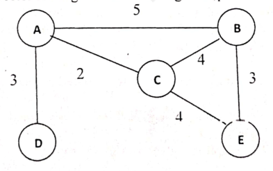20247m
Module 3: Network Layer & Routing
View this question on its own page →Explain the distance vector routing for the following example.
 Worked Solution
Distance vector routing: worked example
Network from the figure (link costs): A–B = 5, A–C = 2, A–D = 3, B–C = 4, B–E = 3, C–E = 4.
Principle
In distance vector routing each router keeps a table of the best-known distance to every destination and the next hop. Periodically it sends its vector (distance to all nodes) only to its direct neighbours. Each router then applies the Bellman-Ford equation:
Dₓ(y) = min over neighbours v of { c(x, v) + Dᵥ(y) }
The process repeats until no table changes (convergence).
Step 0: initial vectors (only direct neighbours known, ∞ = unknown)
Order: [A, B, C, D, E]
Router A B C D E A 0 5 2 3 ∞ B 5 0 4 ∞ 3 C 2 4 0 ∞ 4 D 3 ∞ ∞ 0 ∞ E ∞ 3 4 ∞ 0 Step 1: after the first exchange (using neighbours' initial vectors)
Example calculations:
- A → E: via B = 5 + 3 = 8; via C = 2 + 4 = 6; via D = 3 + ∞. Minimum = 6 (via C).
- B → D: via A = 5 + 3 = 8; via C = 4 + ∞; via E = 3 + ∞. Minimum = 8 (via A).
- C → D: via A = 2 + 3 = 5.
- D → B: via A = 3 + 5 = 8; D → C: via A = 3 + 2 = 5.
- E → A: via B = 3 + 5 = 8; via C = 4 + 2 = 6.
Router A B C D E A 0 5 2 3 6 B 5 0 4 8 3 C 2 4 0 5 4 D 3 8 5 0 ∞ E 6 3 4 ∞ 0 Step 2: after the second exchange
- D → E: via A = 3 + 6 = 9.
- E → D: via B = 3 + 8 = 11; via C = 4 + 5 = 9.
All other entries are unchanged.
Step 3: third exchange gives no change, so the tables have converged
Final routing tables (destination: cost via next hop)
Router To A To B To C To D To E A 0 5 (B) 2 (C) 3 (D) 6 (C) B 5 (A) 0 4 (C) 8 (A) 3 (E) C 2 (A) 4 (B) 0 5 (A) 4 (E) D 3 (A) 8 (A) 5 (A) 0 9 (A) E 6 (C) 3 (B) 4 (C) 9 (C) 0 Example: the best A→E path is A → C → E with cost 2 + 4 = 6. The best D→E path is D → A → C → E with cost 3 + 2 + 4 = 9.
Remarks
- Each router knows only its neighbours and their vectors, not the whole topology.
- Count-to-infinity: if a link fails, wrong information may circulate slowly; it is reduced with split horizon, poison reverse, and triggered updates.
- The protocol used in practice for this method is RIP.
Q6b. Differentiate between forwarding and routing.20217m
Module 3: Network Layer & Routing
View this question on its own page →Differentiate between forwarding and routing.
Worked SolutionForwarding vs Routing
Both are network-layer functions, but they belong to different planes and work at completely different timescales.
Aspect Forwarding Routing Meaning Move a packet from an input link interface to the correct output link interface Determine the end-to-end path (route) a packet must take from source to destination Scope Local — decided by a single router Global — decided collectively by all routers in the network Plane Data plane (packet forwarding) Control plane (routing algorithms) Timescale Per packet — nanoseconds to microseconds Per connection / periodically — milliseconds to minutes Inputs Destination IP address + forwarding table Topology, link costs, metrics, policies, traffic load Mechanism Match (address lookup) + action (switch to output port), using ASICs / switching fabric / TCAM Routing protocols exchange information (DV, LS, path vector) and compute paths Table used Forwarding table: dest prefix → output portRouting table / RIB from which the forwarding table is derived Examples IP longest-prefix match OSPF, RIP, BGP Analogy The signpost at a junction telling you which exit to take Planning the whole trip on the map before leaving Relationship between the two
Routing computes the paths; forwarding uses them. The routing algorithms run in the control plane, place the resulting routes in each router's routing table, and the data plane then installs only the necessary forwarding entries. If a link fails, routing re-computes and the new forwarding table takes effect — forwarding itself never "thinks", it only looks up.
Extra points worth mentioning
- Forwarding is data plane: it happens at every router for every packet and must be hardware-accelerated because line rates are very high.
- Routing is control plane: it runs in software (routing protocols) and runs much less often — on topology changes, periodically, or on policy updates.
- The two can be physically co-located in a traditional router, or separated as in SDN, where a central controller computes routes and pushes forwarding rules to dumb switches (control plane centralised, data plane distributed).
- Both rely on a common view of the network, so a wrong routing decision eventually produces wrong forwarding decisions for every packet on that path.
Q7. An ISP is granted the block 80.70.56.0/21. The ISP needs to allocate addresses for two organizations each with 500 addresses, two organizations each with 250 addresses, and three organizations each with 50 addresses. (a) Find the number and range of addresses in the ISP block. (b) Find the range of addresses for each organization and the range of unallocated addresses.202214m
Module 3: Network Layer & Routing
View this question on its own page →An ISP is granted the block 80.70.56.0/21. The ISP needs to allocate addresses for two organizations each with 500 addresses, two organizations each with 250 addresses, and three organizations each with 50 addresses.
(a) Find the number and range of addresses in the ISP block.
(b) Find the range of addresses for each organization and the range of unallocated addresses.Worked Solution(a) ISP Block 80.70.56.0/21 — Number and Range
Given: network address , prefix .
Step 1 — Number of addresses
Step 2 — Subnet mask: 21 bits = two full octets + 5 bits:
Step 3 — Range: the third octet advances in steps of , starting at 56, so it ends at .
- First address: 80.70.56.0
- Last (broadcast) address: 80.70.63.255
- Check: ✓
Answer (a): 2048 addresses, from 80.70.56.0 to 80.70.63.255.
(b) Allocation to Organisations and Unallocated Range
Sizing rule: give each organisation the next power of two block that can hold the requested number of usable addresses (usable for a normal subnet).
Demand Needed Smallest block Prefix Total addresses Usable (total − 2) 2 × 500 500 /23 512 510 ✓ ≥ 500 2 × 250 250 /24 256 254 ✓ ≥ 250 3 × 50 50 /26 64 62 ✓ ≥ 50 Sequential allocation from 80.70.56.0 upward:
- addresses
- addresses
- addresses
Total used addresses.
Organisation Block Address range Count Org 1 (500) 80.70.56.0/23 80.70.56.0 – 80.70.57.255 512 Org 2 (500) 80.70.58.0/23 80.70.58.0 – 80.70.59.255 512 Org 3 (250) 80.70.60.0/24 80.70.60.0 – 80.70.60.255 256 Org 4 (250) 80.70.61.0/24 80.70.61.0 – 80.70.61.255 256 Org 5 (50) 80.70.62.0/26 80.70.62.0 – 80.70.62.63 64 Org 6 (50) 80.70.62.64/26 80.70.62.64 – 80.70.62.127 64 Org 7 (50) 80.70.62.128/26 80.70.62.128 – 80.70.62.191 64 Unallocated addresses:
(as 80.70.62.192/26 → 64 addresses, plus 80.70.63.0/24 → 256 addresses; ✓).
Answer (b): Org1 → 80.70.56.0–80.70.57.255, Org2 → 80.70.58.0–80.70.59.255, Org3 → 80.70.60.0–80.70.60.255, Org4 → 80.70.61.0–80.70.61.255, Org5 → 80.70.62.0–80.70.62.63, Org6 → 80.70.62.64–80.70.62.127, Org7 → 80.70.62.128–80.70.62.191; unallocated range 80.70.62.192 – 80.70.63.255 (320 addresses).
Q7a. Explain the procedure for checksum and verification in the IPv4 protocol. What part of an IPv4 packet is covered in the checksum calculation and why? Are options, if present, included in the calculation?20158m
Module 3: Network Layer & Routing
View this question on its own page →Explain the procedure for checksum and verification in the IPv4 protocol. What part of an IPv4 packet is covered in the checksum calculation and why? Are options, if present, included in the calculation?
Worked SolutionIPv4 Header Checksum — Computation and Verification
The IPv4 checksum is a simple 16-bit one's-complement checksum used to detect corruption of the IP header only. It is computed by both the sender (to fill the Checksum field) and every receiver/router (to validate the packet).
What part of the packet is covered?
Only the IPv4 header (including the Checksum field itself, the Options field if present, and the Source/Destination addresses) is covered — the data/payload is NOT included.
Why only the header?
- The payload is already protected by the data-link layer FCS (e.g., CRC-32 in Ethernet) and, end-to-end, by the transport layer checksum (TCP/UDP). IP itself is connectionless and need only guarantee that the packet is routed to the correct destination with an intact header.
- Checking the whole packet at every router hop would be far too expensive; instead each hop re-validates the header (and the router must recompute the checksum anyway because the TTL field changes at every hop).
Sender procedure (checksum generation)
- Set the Checksum field to 0 in the header.
- Split the header into 16-bit words (if the header length is odd, pad the last byte with a zero byte).
- Add all the 16-bit words using one's-complement (end-around carry) addition: whenever there is a carry out of bit 15, add it back into bit 0.
- Take the one's complement (invert all bits) of the sum → this value is written into the Checksum field.
where are the 16-bit words and denotes one's complement, with end-around carries.
Receiver procedure (verification)
- Split the received header (Checksum field now included) into 16-bit words.
- Add them all with one's-complement addition.
- If the result is (all ones), the header is accepted as error-free; any other value → the packet is silently discarded (IP reports errors only via ICMP, and never for the source host of a bad header).
Key property: because the checksum is one's-complement, any single-bit error (and any odd number of bit errors in many patterns) is detected; the one's-complement arithmetic is chosen so the computation is order-independent and can be done incrementally.
Are options included?
Yes. The IPv4 header length (IHL) field is variable (5 to 15 32-bit words), and the checksum covers the entire header, including any options — because the Options field lies inside the header, before the payload. Only the payload is excluded. (If options were not covered, an error in options such as the source-route or timestamp fields would go undetected.)
Note: if an image/numerical header is attached to the question, the general procedure above applies — pad to an even number of bytes, zero the checksum field, sum the 16-bit words with end-around carry, and complement.
Q7b. Discuss the functions and the design issues of the network layer in the OSI model.20177m
Module 3: Network Layer & Routing
View this question on its own page →Discuss the functions and the design issues of the network layer in the OSI model.
Worked SolutionNetwork Layer — Functions and Design Issues
The network layer (Layer 3) is responsible for host-to-host delivery of packets across possibly heterogeneous networks, i.e., moving packets from the source host to the destination host through intermediate routers, independent of the underlying physical/link technologies.
Functions of the Network Layer
- Inter-networking / packet delivery: Transfers data from source to destination across multiple networks using routers; each packet is forwarded hop-by-hop.
- Addressing: Uses a hierarchical logical address (IP address) that identifies the host irrespective of physical (MAC) addresses; supports subnetting and CIDR for scalable address allocation.
- Routing: Determines the best path for each packet using routing protocols (RIP, OSPF, BGP) and the routing table built by the forwarding process.
- Forwarding: At each router, moves the packet from the correct input interface to the appropriate output interface based on the destination address.
- Fragmentation and Reassembly: Splits a packet that exceeds the MTU of the outgoing link into fragments (sets offset, MF flag, ID) and reassembles them at the destination.
- Error control, flow control and congestion control: Signalled through ICMP; congestion handling via source quench/RED (IP itself is best-effort).
- Datagram services: Connectionless (datagram) or connection-oriented (virtual circuit) delivery, plus quality-of-service support (TOS field, diffserv).
Design Issues of the Network Layer
Design issue What must be decided 1. Services provided to the transport layer Should the network offer connection-oriented (guaranteed, ordered) or connectionless (datagram) service to the transport layer — and should that choice be visible to the sender? (IP chose connectionless; TCP/UDP add reliability above.) 2. Addressing & service model How hosts and interfaces are named (hierarchical IP addressing) so packets can be located anywhere; how addressing interacts with subnetting/CIDR/NAT. 3. Packet delivery semantics Datagrams vs virtual circuits: independent routing of each packet vs a pre-established path; implications for ordering, duplicate control and QoS. 4. Fragmentation & MTU handling How to handle packets larger than a link's MTU — fragmentation and reassembly, and the per-hop overhead it creates. 5. Routing algorithms & forwarding Choosing shortest/best paths (optimality, correctness, robustness, simplicity, stability, fairness, efficiency) and building forwarding tables. 6. Congestion control Detecting and relieving congestion — buffering vs pacing (leaky bucket), credit schemes, choke packets; where control should sit (network vs hosts). 7. Inter-networking & heterogeneity How to hide differences among networks (addressing, MTU, frame size, maximum packet size) and connect them via routers/gateways. 8. Security & service differentiation Authentication, confidentiality (IPsec), and providing differentiated services (TOS/DiffServ) over a best-effort core. Summary: The network layer must (i) define what service it gives to transport, (ii) how packets are identified and addressed, (iii) how the best path is chosen and packets forwarded, (iv) how large packets are fragmented, and (v) how congestion, heterogeneity and inter-networking are handled — these are the classic design issues, with IP choosing connectionless datagram service and best-effort delivery.
- Install PocketlyBudget App•POCKETLY
Pocketly on Android
Log daily food, travel, and hostel expenses instantly. Set monthly spending limits and see where your money goes without complex spreadsheets.
Q7b. We know that there are 2 types of address scheme (i.e. IP address and MAC address) in computer networks. Explain what is the need of having two types of addresses. What will happen if we use only IP address in computer networks?20237m
Module 3: Network Layer & Routing
View this question on its own page →We know that there are 2 types of address scheme (i.e. IP address and MAC address) in computer networks. Explain what is the need of having two types of addresses. What will happen if we use only IP address in computer networks?
Worked SolutionNeed for Two Types of Addresses: IP Address and MAC Address
Definitions
- MAC (physical / link) address — a 48-bit (6-byte) flat address burned into the NIC by the manufacturer: 3 bytes of OUI (vendor) + 3 bytes of device ID, e.g.
00:1A:2B:3C:4D:5E. It is used by the data-link layer for hop-to-hop delivery on one local network. - IP (logical) address — a 32-bit (IPv4) hierarchical address assigned by the administrator or DHCP: a network part that identifies the network and a host part that identifies the host. It is used by the network layer for end-to-end routing through the internetwork.
Why both are needed
- Different scopes need different structures. IP must be hierarchical so that routers can aggregate: a core router forwards on the network part alone instead of storing millions of individual hosts. MAC addresses are flat and carry no routing information — a routing table built from them would have to list every NIC in the world.
- Different layers do different jobs. The IP address gets the packet to the destination network; the MAC address gets the frame to the next hop and finally to the destination host on that link. Each hop rewrites the frame header (new source MAC of the sender, new destination MAC of the receiver) while the IP header stays unchanged end-to-end.
- Technology independence. Ethernet, 802.11, Bluetooth and PPP each have their own frame format but can all carry the same IP packet. MAC is what makes local delivery possible on the specific medium of that hop.
- Fixed vs changeable. The MAC is tied to the hardware and is permanent; the IP changes when the host moves to another network. Applications can therefore keep using one IP identity while the host roams.
- ARP relies on the pair. A sender knows the destination IP but not the MAC of the next hop; ARP broadcasts a query that is framed with the link-layer broadcast address FF:FF:FF:FF:FF:FF and answered with the target's MAC — a procedure that is impossible without both address types.
What would happen if only IP addresses were used
- No local delivery mechanism. A switch forwards using MAC addresses in the frame. Without them it would have to decapsulate every frame and consult an IP table — every device would behave like a router, adding huge processing cost and latency even inside one LAN.
- Routing tables would explode. IP would have to serve both local identification and global routing. Keeping it flat (like MAC) means every router stores every host; keeping it hierarchical means hosts on the same LAN could not be addressed directly without a router in the path.
- Address resolution breaks. There would be no physical broadcast address, so no way to ask who owns an IP; ARP and DHCP discovery could not be framed.
- Multi-technology networks break. One address format cannot be written into every kind of frame (Ethernet, Wi-Fi, token ring); two devices on the same wireless LAN could never talk directly.
- Every NIC would need globally routable configuration, even for a closed LAN, and changing networks would mean re-addressing the hardware.
Conclusion: IP = where the host is in the internetwork (logical, hierarchical, routable); MAC = who the host is on the local wire (physical, flat, hop-to-hop). The two answer complementary questions, so both are required.
- MAC (physical / link) address — a 48-bit (6-byte) flat address burned into the NIC by the manufacturer: 3 bytes of OUI (vendor) + 3 bytes of device ID, e.g.
Q7b. Explain the responsibility of network and transport layers of OSI model with example.20167m
Module 3: Network Layer & Routing
View this question on its own page →Explain the responsibility of network and transport layers of OSI model with example.
Worked SolutionResponsibilities of the Network and Transport Layers in OSI
Network layer (Layer 3) - packet delivery between hosts
Responsibilities:
- Logical addressing: defines a universal, hierarchical address (IP address) that identifies a host regardless of the underlying LAN technology.
- Forwarding: moves each packet hop-by-hop from the correct input interface to the output interface of every router.
- Routing: computes the path using routing protocols - distance vector (RIP), link state (OSPF), path vector (BGP).
- Packetization and fragmentation/reassembly: encapsulates transport segments into packets and fragments them when a link's MTU is smaller, reassembling only at the destination host.
- Internetworking and diagnostics: routers interconnect dissimilar networks; ARP maps IP to MAC and ICMP reports errors ("destination unreachable", "TTL expired", echo request/reply).
Service: connectionless best-effort datagram service (IP).
Example: a packet from 192.168.1.10 to 8.8.8.8 is handed to the default gateway, routed hop-by-hop using OSPF-derived tables, and if a router's TTL expires it returns an ICMP "Time Exceeded" message.
Transport layer (Layer 4) - end-to-end delivery between processes
Responsibilities:
- Segmentation and reassembly: splits the message into segments and reassembles them in order at the receiver.
- Process multiplexing/demultiplexing: port numbers deliver data to the correct application (80 = web, 53 = DNS, 22 = SSH).
- Connection management: TCP performs the three-way handshake (SYN / SYN-ACK / ACK) and orderly close (FIN/ACK); UDP is connectionless.
- Flow control: the receiver's advertised window prevents the sender from overrunning the receiver's buffer.
- Error control and reliability: sequence and acknowledgment numbers, checksum, ACKs and retransmission on timeout give exactly-once, in-order delivery (TCP).
- Congestion control: slow start, congestion avoidance (AIMD), fast retransmit and fast recovery protect the network itself.
- Low-overhead delivery: UDP provides minimal encapsulation with low delay for real-time applications.
Example: a web page arrives as thousands of TCP segments which may be lost or reordered by IP; TCP numbers, ACKs, retransmits and reorders them so the browser receives one contiguous byte stream.
Comparison
Aspect Network layer Transport layer Addressing unit IP address (host) Port number (process) PDU Packet / datagram Segment (TCP) / datagram (UDP) Scope Host-to-host, hop-by-hop End-to-end, process-to-process Reliability Best effort TCP reliable, UDP unreliable Protocols IP, ICMP, ARP, OSPF, RIP TCP, UDP, SCTP Devices / location Routers, layer-3 switches Implemented in end hosts (OS/kernel) Key idea: the network layer finds and forwards packets between machines, while the transport layer guarantees correct, ordered, congestion-free delivery between applications on those machines.
Q7b. Discuss the types of ICMP messages.20156m
Module 3: Network Layer & Routing
View this question on its own page →Discuss the types of ICMP messages.
Worked SolutionICMP Message Types
ICMP (Internet Control Message Protocol) is a network-layer (IP) companion protocol used to report errors and send operational/query messages (e.g., ping) between hosts and routers. ICMP messages are carried inside IP datagrams; the ICMP header starts with 1 byte Type, 1 byte Code, 2 bytes Checksum, followed by type-dependent data.
1. Error Messages (destination-unreachable / informational)
Type Message Typical Code values & meaning 3 Destination Unreachable 0 network, 1 host, 2 protocol, 3 port unreachable; 4 fragmentation needed & DF set 4 Source Quench Congestion — sender should slow down (obsolete, deprecated) 5 Redirect 0 redirect for network, 1 for host, 2 for TOS+network, 3 TOS+host — used by a router to tell the source a better first hop 11 Time Exceeded 0 TTL expired in transit (traceroute), 1 fragment reassembly time exceeded 12 Parameter Problem Error in the IP header field (pointer gives the offending byte) 3, 4, 5 (Type 3/9/10/13/14) Fragmentation / Filtering problems 4 fragmentation needed, 9/10 admin prohibited (firewall filtering) Error messages are never generated for ICMP error messages themselves (to avoid infinite loops). The IP header + 8 bytes of the original datagram that caused the error are included so the source can identify the offending packet.
2. Query Messages (informational / request–reply pairs)
Type Message Purpose 0 / 8 Echo Reply / Echo Request ping — test reachability and RTT of a host 13 / 14 Timestamp Request / Reply Measure round-trip time and synchronize clocks 17 / 18 Address Mask Request / Reply Host asks subnet mask from a router 9 / 10 Router Advertisement / Solicitation A host discovers available routers on a link Summary: Error messages report problems (types 3, 4, 5, 11, 12), while query messages are request–reply pairs used for diagnostics (echo, timestamp, mask, router discovery). ICMP handles only error/control reporting, never delivery of user data.
Q7b. With a neat diagram, explain distance vector routing protocol.20217m
Module 3: Network Layer & Routing
View this question on its own page →With a neat diagram, explain distance vector routing protocol.
Worked SolutionDistance Vector Routing
Distance vector routing is a distributed, iterative, asynchronous algorithm based on the Bellman-Ford equation. Each router maintains a table (a "vector") giving the best-known distance to every destination and the next hop towards it, and exchanges this vector only with its immediate neighbours. No router ever learns the full topology. Example protocol: RIP (uses hop count, max 15 hops).
Principle
The least cost from x to y is the cheapest of: the direct cost to a neighbour v plus v's currently known least cost to y. Each router repeatedly advertises its vector, applies the equation to the neighbours' advertisements, and updates its table until no entry changes (convergence).
Network diagram
           2                3
      A --------- B --------------- C
       \                       /
        \                     /
         4                   5
          \                 /
           \               /
             ------ D ----

   (A-B = 2, B-C = 3, A-D = 4, D-C = 5)
Operation at router A
- Initialisation (only direct links): A knows A = 0, B = 2 (via B), D = 4 (via D), C = ∞.
- First exchange: A receives vectors from neighbours B and D.
- B advertises: "I can reach C in 3 hops, D in ∞, myself 0."
- D advertises: "I can reach C in 5 hops, B in ∞, myself 0."
- Apply Bellman-Ford:
- C: min(∞, 2 + 3, 4 + 5) = 5 via B
- B: min(2, 4 + ∞) = 2 (unchanged) — D: min(4, 2 + ∞) = 4 (unchanged)
- Table now stable (converged).
Final distance table at A:
Destination Cost Next hop A 0 — B 2 B C 5 B D 4 D The same computation runs simultaneously in every router, each building its own table from its neighbours' vectors.
Properties
Aspect Detail Knowledge Local — only neighbours' vectors, no global topology Communication Periodic (RIP: every 30 s) and on-change updates to neighbours only Advantages Simple, minimal computation, very low overhead, little memory Disadvantages Count-to-infinity problem, transient routing loops, slow convergence after a failure Remedies Split horizon, poison reverse, triggered updates, hold-down timers Cost metric Must be additive (hop count, delay) — unlike link state, which can use any metric Summary: each router "believes" its neighbours about destinations it does not know directly, so a bad or stale advertisement propagates slowly and can drive the cost to infinity during a failure — the main weakness compared with link state routing.
Q8a. Discuss four types of link defined by OSPF. What is the basis of classification for the four types of link defined by OSPF?20158m
Module 3: Network Layer & Routing
View this question on its own page →Discuss four types of link defined by OSPF. What is the basis of classification for the four types of link defined by OSPF?
Worked SolutionOSPF Link Types
OSPF (Open Shortest Path First) is a link-state interior gateway protocol. In its topology database, OSPF does not model just point-to-point connections — every adjacency is classified as one of four link types.
Basis of classification
The classification is based on (a) how the two endpoints (routers) are connected — i.e., the nature of the connection between the routers, and (b) whether each endpoint has a neighbour on that link / whether both ends belong to the same routing domain (area). In practice OSPF decides the type from the configured interface type and whether the far end is another router, a network segment, or an AS boundary.
The four link types
Link type Description Point-to-point link Connects exactly two routers directly (e.g., a serial line / leased line). No other host or router is on the link, so no addressing/broadcast issue arises. Both routers become adjacent and exchange LSAs directly. Transit link (broadcast network) A network (e.g., Ethernet, Token Ring) that can support multiple (three or more) routers and broadcast/multicast. A Designated Router (DR) and Backup DR (BDR) are elected to limit the number of adjacencies (full mesh avoided) and to flood LSAs to all attached routers. Stub link A network that connects to exactly one router (a "dead end"). Hosts on such a link reach the rest of the internetwork only through that single router. OSPF advertises it as a stub network (LS type 3) — it is not used to reach other routers. Virtual link A logical, configured link through a non-backbone area to connect an area that is physically disconnected from area 0 (backbone). It acts like a point-to-point link, but is really a tunnel through one or more intermediate routers; must run within a single area. Why the classification matters
- Point-to-point vs transit determines whether OSPF forms adjacencies with every neighbour or only with the DR/BDR — this controls LSA flooding overhead.
- Stub links are simply advertised as reachable networks, avoiding unnecessary router-to-router routing.
- Virtual links keep the rule "all areas must be physically connected to area 0" satisfied even in poorly planned topologies.
In short, OSPF classifies links by the number/kind of endpoints attached to the segment and the connectivity role of the link in the OSPF hierarchy.
Q8a. What are the functions of a RIP message? List the RIP shortcomings and their corresponding fixes.20167m
Module 3: Network Layer & Routing
View this question on its own page →What are the functions of a RIP message? List the RIP shortcomings and their corresponding fixes.
Worked SolutionFunctions of a RIP Message, Shortcomings and Their Fixes
Functions of a RIP message
RIP (Routing Information Protocol) is a distance-vector protocol that exchanges routing information in UDP datagrams (port 522) with directly connected neighbours. Its message functions are:
- Request message: asks neighbours to send part or all of their routing tables. Sent at router startup (to discover neighbours) or when a router suspects an inconsistency.
- Response message (update): carries routing entries - address family, IP address, next hop and metric (hop count). Sent
- every 30 s as a periodic full-table update,
- as a triggered (partial) update immediately when a route changes or a link fails,
- as a direct reply to a request message.
- Route lifetime management: an entry becomes invalid after 180 s without an update (enters hold-down) and is flushed after 240 s - this ages out stale routes.
- RIPv2 additions: carries subnet masks (VLSM/CIDR), next-hop address, route tags, multicast updates to 224.0.0.9 and authentication data.
Shortcomings of RIP and their corresponding fixes
Shortcoming Corresponding fix Count-to-infinity - loops and extremely slow convergence when a link fails Split horizon, poison reverse, hold-down timers, triggered updates, and the hard metric cap of 15 hops Metric is only hop count - a 64-kbps link can be preferred over a 1-Gbps link Use a bandwidth/delay-aware metric: OSPF cost (based on bandwidth) or EIGRP's composite metric Periodic full-table flooding every 30 s wastes bandwidth Triggered (event-driven) and partial updates Slow convergence due to periodic updates Triggered updates + hold-down timers; otherwise migrate to link-state routing (OSPF) No authentication - a rogue router can poison routes RIPv2 simple password / MD5 authentication Classful, no subnet mask / VLSM support RIPv2 advertises subnet masks and supports CIDR; uses multicast instead of broadcast Poor scalability (15-hop limit, no route redistribution policy) Move to OSPF/IS-IS (link state) or BGP (path vector) Single path only (no load balancing on unequal paths) Equal-cost multi-path (ECMP) in OSPF, or adaptive routing Summary: RIP's simplicity makes it easy to configure for small networks, but its hop-count metric, periodic updates and count-to-infinity behaviour are fundamental limitations. Split horizon, poison reverse, hold-down and triggered updates mitigate them locally, while OSPF removes the causes by using link-state flooding with a cost metric.
Q8b. Differentiate between Static Routing and Dynamic Routing.20177m
Module 3: Network Layer & Routing
View this question on its own page →Differentiate between Static Routing and Dynamic Routing.
Worked SolutionStatic Routing vs Dynamic Routing
Static routing uses routes that are manually configured by a network administrator and do not change unless edited by hand. Dynamic routing uses routing protocols that automatically discover routes and update the routing table whenever the topology changes.
Parameter Static Routing Dynamic Routing Configuration Entries entered manually by the administrator Learned automatically via routing protocols (RIP, OSPF, EIGRP, BGP) Route updates No automatic update; change only by manual edit Continuous/triggered periodic updates; table rebuilt as topology changes Adaptability to failure Cannot adapt — traffic must be manually re-routed after a link failure Automatically detects failures and recomputes alternate paths Topology changes Needs human intervention Self-adjusting, converges to new state Implementation complexity Simple to configure for small/stable networks Complex — requires protocol tuning, metric/area design, troubleshooting Overhead / resources No bandwidth or CPU overhead for protocols Consumes CPU and link bandwidth for hellos, LSAs, updates Scalability Poor — one entry per destination, unmanageable in large networks Excellent — scales with summarisation, areas, hierarchical design Security More secure (no routing advertisements exchanged) Vulnerable to rogue updates unless authenticated (OSPF MD5, etc.) Convergence Immediate (static), but only if correct Depends on protocol — fast for link-state, slower for distance-vector Suitability Small, stub/leaf networks, default routes, lab setups, cost-sensitive links Large, complex, multi-path, frequently changing networks Loop possibility None (single fixed path) Possible during convergence; controlled by split horizon, holddown, SPF Metric used None — preference is administrative Cost, bandwidth, delay, hop count, load, reliability Key discussion points
- Static is deterministic: the administrator fully controls the path, which is useful for security-sensitive or backup routes (e.g., a default route to an ISP), but it is labour-intensive and fails silently on link failure.
- Dynamic protocols exchange reachability information: distance-vector (RIP) shares neighbour distance vectors with count-to-infinity issues, while link-state (OSPF) floods the whole topology and each router runs Dijkstra independently, converging quickly and loop-free.
- Hybrid designs are common: dynamic routing inside the enterprise with static/default routes at the edge, and static redistribution where appropriate.
Conclusion: Static routing trades flexibility for simplicity/low overhead and suits small stable networks; dynamic routing trades protocol overhead and complexity for automatic adaptation and scalability — essential for large, changing networks.
Q8b. List RIP shortcomings and their corresponding fixes.20156m
Module 3: Network Layer & Routing
View this question on its own page →List RIP shortcomings and their corresponding fixes.
Worked SolutionRIP — Shortcomings and Their Fixes
RIP (Routing Information Protocol) is a distance-vector IGP that uses hop count as its metric with a maximum of 15 hops (16 = unreachable) and exchanges full routing tables every 30 s.
# Shortcoming of RIP Consequence Corresponding fix / remedy 1 Metric is only hop count (max 15) — ignores bandwidth, delay, congestion A 2-hop low-speed link may be preferred over a 1-hop high-speed link; large networks unreachable Use a richer metric: OSPF/EIGRP use cost/bandwidth+delay; RIP has no real fix (limitation of the protocol) 2 Count-to-infinity problem on link failure Routers keep incrementing an unreachable metric, taking minutes to converge Split horizon with poison reverse, hold-down timers, triggered updates; alternatively use LS routing (OSPF) which does not suffer from it 3 Convergence is slow (30 s periodic updates + timers) Transient black holes and routing loops during topology change Triggered (flash) updates on change, shorter timers; or switch to link-state protocols that flood changes immediately 4 Full routing table advertised every 30 s regardless of change Wasteful bandwidth, especially on slow/wireless links Triggered updates (send only on change); route redistribution/filtering; VLSM support via RIPv2 5 No VLSM / classful routing (RIPv1) Cannot summarise or support variable-length masks, poor address utilisation RIPv2 — carries subnet masks in updates, supports CIDR summarisation, authentication, and multicast (224.0.0.9) 6 No authentication of updates (RIPv1) Susceptible to rogue/malicious routing advertisements RIPv2 authentication (plain/md5) of routing updates 7 No support for multiple metrics / equal-cost paths; simple Bellman–Ford only; loop-free property weak Sub-optimal routes Use OSPF/IS-IS/EIGRP for large or multi-vendor networks Summary: RIP's core weaknesses — hop-count metric, slow periodic convergence, and count-to-infinity — are addressed within the RIP family by triggered updates, split horizon/poison reverse, hold-down timers, RIPv2 (VLSM/CIDR/authentication); the complete engineering fix is to migrate to a link-state protocol (OSPF) for larger networks.
Q9a. Compare the following terms: (a) ARP vs RARP201914m
Module 3: Network Layer & Routing
View this question on its own page →Compare the following terms: (a) ARP vs RARP
Worked SolutionARP vs RARP (Address Resolution Protocol vs Reverse Address Resolution Protocol)
Both are network-layer support protocols that map between a device's IP (logical) address and its MAC (physical) address, but they perform exactly opposite mappings.
1. Basic definitions
- ARP resolves a known IP address → unknown MAC address. When a host knows the destination's IP (e.g. from DNS) but must build an Ethernet frame, it broadcasts an ARP request on the LAN; the owner of that IP replies with its MAC, which is then cached in the ARP table.
- RARP resolves a known MAC address → unknown IP address. A diskless station that knows only its own MAC (read from the NIC) broadcasts a RARP request asking "what is my IP?"; a RARP server on the LAN replies with the assignment.
2. Comparison table
Basis ARP RARP Direction of mapping IP address → MAC address MAC address → IP address Who uses it Any host/router that needs to frame a packet Diskless/thin client that boots without local IP configuration Protocol layer Network layer, just above the data link layer (operates over Ethernet) Network layer, just above the data link layer Message types ARP request (broadcast) / ARP reply (unicast), also reverse ARP & gratuitous ARP RARP request (broadcast) / RARP reply (unicast) Server needed No server required — any host answers for itself Dedicated RARP server required on every LAN Configuration stored In each host's ARP cache (dynamic + static entries) Centralised on the RARP server (file/database) Message format Same 28-byte packet for both request and reply (hardware type, protocol type, hlen/plen, opcode, SHA/SPA/THA/TPA) Same format as ARP with opcode 3/4 Broadcast used Only when the MAC for a target IP is not in the cache Always, since the client has no IP and cannot use IP-based services Limitations Cannot cross routers (broadcast domain); prone to ARP spoofing/poisoning LAN-limited, servers must be on the same segment; largely obsolete Replaced/superseded by Still fundamental to IPv4 (proxy ARP, gratuitous ARP) BOOTP and DHCP, which also supply subnet mask, default gateway, DNS, etc. Direction of query "Who has 192.168.1.5? Tell 192.168.1.10" "I am 00:AA:BB:CC:DD:EE; what is my IP?" 3. Operational flow
ARP (IP → MAC):
- Host A wants to send to 192.168.1.5 and checks its ARP cache — entry missing.
- A broadcasts an ARP request: "Who has 192.168.1.5?".
- Every host on the LAN receives it; only the owner of 192.168.1.5 replies unicast: "192.168.1.5 is at 00:11:22:33:44:55".
- A stores the pair in its ARP cache (typically 15–45 min TTL) and now frames the actual data.
RARP (MAC → IP):
- Diskless machine B reads its MAC 00:AA:BB:CC:DD:EE at boot.
- B broadcasts a RARP request: "My MAC is 00:AA:BB:CC:DD:EE, what is my IP?".
- The RARP server on that LAN looks up the MAC in its table and unicasts back the assigned IP (and the server's own IP).
- B configures its network interface and continues booting.
4. Key differences in one line
ARP lets an already-configured host reach other hosts on the link by discovering hardware addresses for known IP addresses; RARP lets an unconfigured host discover its own IP from its hardware address — a capability now provided by BOOTP/DHCP.
Q9a. Explain the following terms: (a) Border Gateway Protocol20177m
Module 3: Network Layer & Routing
View this question on its own page →Explain the following terms: (a) Border Gateway Protocol
Worked SolutionBorder Gateway Protocol (BGP)
BGP (Border Gateway Protocol) is the exterior gateway routing protocol of the Internet, used to exchange reachability (routing) information between Autonomous Systems (AS) — the current standard is BGP-4 (RFC 4271), a path-vector protocol.
Key characteristics
- Classless and path-vector: each BGP update advertises the complete AS-PATH to a destination network, so the receiver can detect and reject routing loops by checking whether its own AS already appears in the path.
- Policy-based: unlike interior protocols that optimise a metric, BGP lets an AS choose routes based on administrative policy (commercial relationships, traffic engineering, filtering) rather than shortest path.
- Runs over TCP (port 179): TCP provides reliable, ordered delivery, so BGP needs no own retransmission/sequencing; neighbours establish a TCP connection first, then open a BGP session.
Operation
- Peering: Two BGP routers (peers) form a TCP connection and complete an OPEN handshake (version, AS number, hold timer, BGP ID).
- Keep-alive: Periodic KEEPALIVE messages maintain the session; if none arrive within the hold time, the session drops.
- Update: Only incremental, changed information is advertised (network layer reachability info + path attributes such as ORIGIN, AS_PATH, NEXT_HOP, LOCAL_PREF, MED, communities).
- Notification: On errors, a NOTIFICATION message is sent and the session is closed.
Path attributes & route selection (simplified)
Attribute Role ORIGIN (IGP/EGP/incomplete) How the route was learned AS_PATH Sequence of ASes traversed — loop prevention & policy NEXT_HOP IP address of the next router on the path to the destination LOCAL_PREF Preference for exit points within an AS (higher preferred) MED Suggestion to neighbouring AS which of several entry points to use (lower preferred) The decision order is roughly: highest LOCAL_PREF → shortest AS_PATH → lowest origin type → lowest MED → lowest router ID.
iBGP vs eBGP
- eBGP: between routers in different ASes (external peers).
- iBGP: within the same AS — distributes externally learned routes to internal routers; iBGP routes are not re-advertised to other iBGP peers (hence the need for full-mesh or route reflectors).
Significance: BGP is the glue of the global Internet (~1 million+ routes in the default-free zone) — every packet crossing the Internet relies on the AS paths that BGP exchanges, and its policy control is what allows inter-domain business relationships to be enforced.