
2024 question paper
Robotics Control System
23 questions
Q1a. For LQR, the cost function is J = \int (x^TQx + u^TRu)dt, minimize for Q = I, R = 1. What is the control input u? (i) -Kx (ii) -K (iii) Qx (iv) Ru20242m
Unit 6.0: Design of Controllers
View this question on its own page →For LQR, the cost function is , minimize for . What is the control input u?
(i)
(ii)
(iii)
(iv)Q1b. A system is observable if: (i) States can be measured from outputs (ii) Inputs are visible (iii) Poles are real (iv) Transfer function exists20242m
Unit 2.0: Mathematical Modelling
View this question on its own page →A system is observable if:
(i) States can be measured from outputs
(ii) Inputs are visible
(iii) Poles are real
(iv) Transfer function existsQ1c. Which sensor is used for measuring displacement? (i) Thermistor (ii) LVDT (iii) Photodiode (iv) Bimetallic strip20242m
Unit 1.0: Introduction to Control System
View this question on its own page →Which sensor is used for measuring displacement?
(i) Thermistor
(ii) LVDT
(iii) Photodiode
(iv) Bimetallic stripQ1d. Why are electrical analogies used in control systems? (i) For heating purposes (ii) To make the system unstable (iii) For simplified modeling (iv) To avoid complexity20242m
Unit 2.0: Mathematical Modelling
View this question on its own page →Why are electrical analogies used in control systems?
(i) For heating purposes
(ii) To make the system unstable
(iii) For simplified modeling
(iv) To avoid complexityQ1e. Why is feedback used in a control system? (i) To reduce the cost (ii) To eliminate the use of actuators (iii) To increase accuracy and stability (iv) To increase time delay20242m
Unit 1.0: Introduction to Control System
View this question on its own page →Why is feedback used in a control system?
(i) To reduce the cost
(ii) To eliminate the use of actuators
(iii) To increase accuracy and stability
(iv) To increase time delayQ1f. What is the function of a relay in a control system? (i) Power supply (ii) Sensor feedback (iii) Switching device (iv) None of these20242m
Unit 1.0: Introduction to Control System
View this question on its own page →What is the function of a relay in a control system?
(i) Power supply
(ii) Sensor feedback
(iii) Switching device
(iv) None of theseQ1g. A system has poles at -2 and -4. What can be said about its time response? (i) Oscillatory (ii) Slow response (iii) Overdamped (iv) Underdamped20242m
Unit 3.0: Time Response Analysis
View this question on its own page →A system has poles at and . What can be said about its time response?
(i) Oscillatory
(ii) Slow response
(iii) Overdamped
(iv) UnderdampedQ1h. What is the primary effect of a derivative controller? (i) Increase steady-state error (ii) Increase rise time (iii) Reduce overshoot (iv) Increase error20242m
Unit 6.0: Design of Controllers
View this question on its own page →What is the primary effect of a derivative controller?
(i) Increase steady-state error
(ii) Increase rise time
(iii) Reduce overshoot
(iv) Increase errorQ1i. For system A = \begin{bmatrix} 0 & 1 \\ -1 & -3 \end{bmatrix}, B = \begin{bmatrix} 0 \\ 1 \end{bmatrix}, check controllability using rank. (i) Rank = 2, controllable (ii) Rank = 1, uncontrollable (iii) Rank = 2, not observable (iv) Rank = 1, observable20242m
Unit 2.0: Mathematical Modelling
View this question on its own page →For system , , check controllability using rank.
(i) Rank = 2, controllable
(ii) Rank = 1, uncontrollable
(iii) Rank = 2, not observable
(iv) Rank = 1, observableQ1j. In the Sketch for Nyquist plot of G(s)H(s) = 1 - (s + 1), Will it encircle (-1+j0) point? (i) Yes (ii) No (iii) Only at high gain (iv) none20242m
Unit 5.0: Stability & Frequency Response Analysis-II
View this question on its own page →In the Sketch for Nyquist plot of , Will it encircle () point?
(i) Yes
(ii) No
(iii) Only at high gain
(iv) none- Install PocketlyBudget App•POCKETLY
Pocketly on Android
Log daily food, travel, and hostel expenses instantly. Set monthly spending limits and see where your money goes without complex spreadsheets.
Q2a. Draw the root locus for G(s)H(s) = \frac{k}{s(s^2 + 2s + 5)} and find the range of 'k' for stability.20247m
Unit 4.0: Stability & Frequency Response Analysis-I
View this question on its own page →Draw the root locus for and find the range of 'k' for stability.
Q2b. Find the number of poles in the left half-plane, the right half-plane, and on the j\omega-axis for the characteristic equation p(s) = 2s^5 + 3s^4 + 2s^3 + 3s^2 + 2s + 1 = 020247m
Unit 4.0: Stability & Frequency Response Analysis-I
View this question on its own page →Find the number of poles in the left half-plane, the right half-plane, and on the -axis for the characteristic equation
Q3a. The block diagram of a simple servo system is shown below 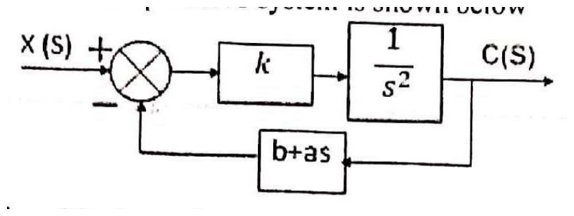 (i) If k = 10, determine the values of 'a' and 'b' to give an overshoot of 16\% and a time constant of 0.1 sec to a unit step input. (ii) Determine t_r, t_p, \omega_d and t_{ss} if k = 40.20247m
Unit 3.0: Time Response Analysis
View this question on its own page →The block diagram of a simple servo system is shown below

(i) If , determine the values of 'a' and 'b' to give an overshoot of and a time constant of sec to a unit step input.
(ii) Determine , , and if .Q3b. Design a basic block diagram of a temperature control system and identify the sensor, controller, and actuator in the system.20247m
Unit 1.0: Introduction to Control System
View this question on its own page →Design a basic block diagram of a temperature control system and identify the sensor, controller, and actuator in the system.
Q4. Draw the Bode plot for the transfer function and find the P.M. & G.M. G(s) = \frac{200(s + 2)}{s(s^2 + 10s + 100)}202414m
Unit 4.0: Stability & Frequency Response Analysis-I
View this question on its own page →Draw the Bode plot for the transfer function and find the P.M. & G.M.
Q5a. With the help of a block diagram, explain the working of a liquid level control system.20247m
Unit 1.0: Introduction to Control System
View this question on its own page →With the help of a block diagram, explain the working of a liquid level control system.
Q5b. The SFG of a control system is shown in the figure below. Find the transfer function C/R. 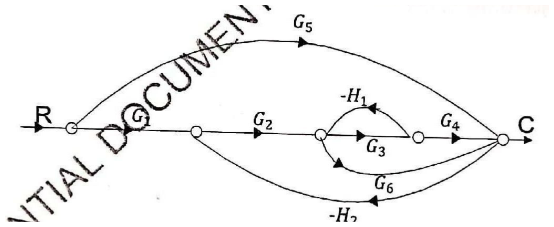20247m
Unit 2.0: Mathematical Modelling
View this question on its own page →The SFG of a control system is shown in the figure below. Find the transfer function .

Q6a. The open-loop transfer function of a unity feedback system is given by G(s) = \frac{k}{s(1 + sT)} where k and T are positive constants. By what factor should the amplifier gain be reduced so that the peak overshoot of the unit-step response of the system is reduced from 75\% to 25\%.20247m
Unit 3.0: Time Response Analysis
View this question on its own page →The open-loop transfer function of a unity feedback system is given by
where and are positive constants. By what factor should the amplifier gain be reduced so that the peak overshoot of the unit-step response of the system is reduced from to .Q6b. Explain how relays, switches, and contactors are used in implementing simple and sequential control systems. Provide a schematic example of a motor control circuit.20247m
Unit 1.0: Introduction to Control System
View this question on its own page →Explain how relays, switches, and contactors are used in implementing simple and sequential control systems. Provide a schematic example of a motor control circuit.
Q7. Consider a closed-loop system with an open-loop transfer function G(s)H(s) = \frac{10(s + 0.5)}{s^2(s + 2)(s + 10)} Apply the Nyquist stability criterion to determine the closed-loop stability of the system.202414m
Unit 5.0: Stability & Frequency Response Analysis-II
View this question on its own page →Consider a closed-loop system with an open-loop transfer function
Apply the Nyquist stability criterion to determine the closed-loop stability of the system.- Install PocketlyBudget App•POCKETLY
Pocketly on Android
Log daily food, travel, and hostel expenses instantly. Set monthly spending limits and see where your money goes without complex spreadsheets.
Q8a. Explore the impact of proportional (P), Integral (I) and Derivate (D) Control modes, individually and in combination (PI, PD, PID) on system performance.20247m
Unit 6.0: Design of Controllers
View this question on its own page →Explore the impact of proportional (P), Integral (I) and Derivate (D) Control modes, individually and in combination (PI, PD, PID) on system performance.
Q8b. Consider the mechanical system shown in the figure below. Find the transfer function G(s) = \frac{V_1(s)}{F(s)} 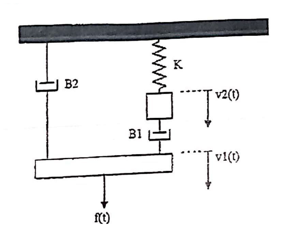20247m
Unit 2.0: Mathematical Modelling
View this question on its own page →Consider the mechanical system shown in the figure below. Find the transfer function

Q9. Write short notes on any two of the following: (a) Significance of actuators and sensors (b) Phase Margin and Gain Margin (c) LQR control (d) Sensitivity of open-loop & closed-loop control system & its effects202414m
Unit 1.0: Introduction to Control System
View this question on its own page →Write short notes on any two of the following:
(a) Significance of actuators and sensors
(b) Phase Margin and Gain Margin
(c) LQR control
(d) Sensitivity of open-loop & closed-loop control system & its effects
Pocketly on Android
Log daily food, travel, and hostel expenses instantly. Set monthly spending limits and see where your money goes without complex spreadsheets.